29
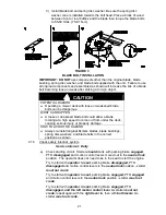
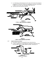
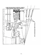
FIGURE 7
SWIVEL ADJUSTMENT
SPRING COMPRESSION ADJUSTMENT
j)
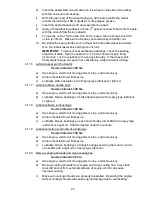
Recheck that blocks fit just snugly under the deck skirt and that the tension
on all the chains are approximately equal. Make sure all chain attachment
bolts are tight.
k) Raise deck lift lever to the 4.5” (11.4 cm) cutting height position (also
transport position, See Figure 6. Adjust spring compression until proper
distance is obtained between the two washers (See Figure 7) by turning the
nut at the front of each spring. Lock nuts in position with jam nuts.
l)
Reposition anti-scalp rollers and tighten securely.
NOTE: When above adjustments have been made, the front of
the deck will be slightly lower than the rear of the deck.
4.2.3
Pump Drive Belt Tension.
Self-tensioning - No adjustment necessary.
4.2.4
Deck Belt Tension.
Self-tensioning - No adjustment necessary.
4.2.5
Adjust Seat Switch.
a) If necessary, adjust the seat actuator rod length to where the machine will
shut off when the operator raises off the seat (with
brake disengaged
or
PTO engaged
) but will continue to run with operator in seat (a slight shift in
weight should not shut machine off). Normal adjustment is when length of
spring is 2.09” (5.3 cm ) (with seat up).
NOTE: To prevent rough ground cut-outs the unit is equipped with a
time delayed seat switch. When the operator raises off the seat with
either the brake disengaged or the PTO engaged, the engine should
stop after 1/2 second has elapsed.
b) To adjust seat switch, loosen lock nut on bottom of the actuator rod (5/16 x 7”
bolt) and adjust the nuts to move the actuator plate up or down on the rod.
4.2.6
Park Brake Adjustment.
a) Stop engine, wait for all moving parts to stop, and remove key.
b) Disengage the park brake.
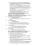
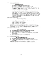
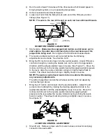
c) There are two different park brakes available for your unit. See Figures 8 & 9
to determine if Type A or Type B is installed on your unit.
d) Loosen the jam nuts next to the yoke at each end of the park brake linkage.
See Figure 8 or 9.
e) Place a wrench on one of the two nuts near the front of the park brake
linkage.
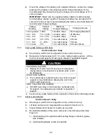
10 1/2" (26.7 cm) For 44” Deck
10” (25.4 cm) For 48” Deck
9 1/2" (24.1 cm) For 52” & 60” Deck
ADJUST FRONT DECK
HEIGHT HERE
Summary of Contents for Lazer ZCT
Page 1: ...For Serial Nos 600 000 Higher Part No 109 2279 Rev B ...
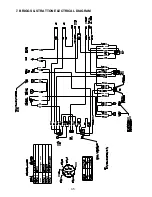
Page 40: ...35 7 BRIGGS STRATTON ELECTRICAL DIAGRAM ...
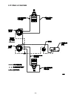
Page 41: ...36 8 HYDRAULIC DIAGRAM ...
Page 44: ... 39 NOTES ...
Page 45: ... 40 NOTES ...
Page 46: ... 41 SERVICE RECORD Date Description of Work Done Service Done By ...
Page 47: ... 42 ...

