1.4 Description
1.4.1 Design
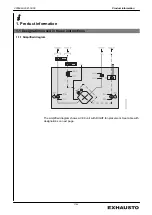
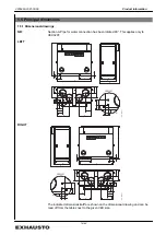
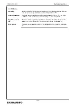
General drawing
The drawing below illustrates the construction of the VEX unit, without doors:
LEFT
RIGHT
9
6
4
17
16
15
14
1,2
2,1
13
12
11
1
2
R
D
14061-
0
1
3
7
8
10
1,1
2,2
5
2
4
6
1
11
12
13
9
14
15
16
17
1
,
2
2
,
1
R
D
14060-
0
1
3
7
8
10
2
,
2
1
,
1
5
Pos. Part
Function
1
Panel filter for extract air
Filters extract air
2
Heating/cooling coil for
supply air (option)
Heats or cools the supply air
3
Condensation tray (option) Collects the condensate and drains it away from the cooling coil to the
condensation outlet
4
Supply air fan
Admits air into the room
5
Spigot for condensation
outlet under cooling coil
(option)
Conducts condensate away from the cooling coil condensation tray.
External condensation outlet connects here.
6
Counterflow heat ex-
changer
Conducts heat from extract air to supply air
7
Condensation tray
Collects the condensate and drains it away from the counterflow heat
exchanger to the condensation outlet
8
Spigot for condensation
outlet under counterflow
heat exchanger
Collects condensate from counterflow heat exchanger condensation
tray. External condensation outlet connects here.
9
Extract air fan (exhaust
air)
Removes "stale" air
10
Bypass damper
With closed damper: In operation with heat recovery, the air passes
through the counterflow heat exchanger.
With open damper: Bypass operation, directs air around the counter-
flow heat exchanger
11
Bypass motor
Opens/closes bypass damper.
12
Panel filter for outdoor air
Filters outdoor air
3005993-2021-03-09
Product information
12/44
Summary of Contents for VEX300 Series
Page 44: ......


