Exakt 80E Plus + Operating Instructions Manual Download Page 46

Unit description 

44 

Edition 09/2016 

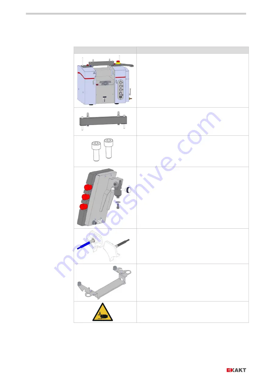
7.11. SCOPE OF DELIVERY 


Symbol 

Meaning 


Base unit 

(

roller material: either  

- hard chrome plated steel  
- tungsten carbide coated steel 

- aluminum oxide


- silicon carbide 


Load traverse (installed for delivery) 

(To lift the machine and to secure it in the 
transport box).  
Keep lifting gear after installation! 


Socket head screws M8x20 
(are required after removing the load traverse, 
see chapter  
9.2 


Dismounting the load traverse).


Operating unit with holder 


Plastic guides (at customer's option) 


Cleaning guard 


Safety device nip gap, various - at customer's 
option, but at least one 

Summary of Contents for 80E Plus +

Page 1: ...s 1 27891EN 900 02 Edition 02 2017 Article number 27891EN 27891EN 900 02 Edition 02 2017 EN Translation of the original operating instructions English THREE ROLLER MILL Operating Instructions Document...

Page 2: ......

Page 3: ...nces and coolants lubricants 16 4 9 Cleaning agents 17 5 Performance specifications 18 5 1 Intended use 18 5 2 No release for work in potentially explosive atmosphere 19 5 3 Reasonably foreseeable mis...

Page 4: ...ces 32 7 5 1 Cleaning 32 7 5 2 Routine operations 33 7 6 Safety marks 34 7 6 1 Danger of crushing 34 7 6 2 Danger of cuts 34 7 6 3 Voltage 35 7 6 4 Increased leakage current 35 7 6 5 Tempering fluid 3...

Page 5: ...68 9 5 1 Temperature control unit 68 9 5 2 With pressureless cooling 69 9 5 3 With pressure cooling 70 9 6 Checklist installation 70 10 Setup 71 10 1 Cleaning the machine housing 71 10 2 Scraper knife...

Page 6: ...110 12 2 1 Pre cleaning the rollers 110 12 2 2 Preparing for cleaning 110 12 2 3 Cleaning roller 1 112 12 2 4 Cleaning roller 2 and roller 3 112 12 3 Cleaning the scraper system 113 12 4 Temperature...

Page 7: ...ort term shutting down 136 16 2 Long term shutting down 136 16 3 Putting out of operation 136 17 Disposal 137 17 1 Disposing of packaging 137 17 2 Disposing operating materials and cleaning agents 137...

Page 8: ...Technologies GmbH Text layout EXAKT Advanced Technologies GmbH Illustrations EXAKT Advanced Technologies GmbH This documentation is copyrighted by EXAKT Without prior written approval the documentatio...

Page 9: ...nstructions are shown in the table below We additionally recommend to read the entire operating instructions before the machine is delivered to you Especially when ordered option article no Chapter 4...

Page 10: ...l be carried out Explanation of the symbols in these instruction DANGER Indicates an exceptionally severe danger situation Disregarding this note will cause lethal or severe irreversible injuries WARN...

Page 11: ...of voltage Warning of rollers rotating reversely Danger of cuts Hot surface Suspended load Danger of hand injuries Danger of crushing Danger of tripping Warning of toxic substances Warnung of explosiv...

Page 12: ...indicates that a special tool or consumables are required Bulleted list Properties of the unit or individual components are listed in bulleted lists 1 Operating sequence Operating sequences instruct...

Page 13: ...horizontally The installation location must ensure safe stand of the unit Place the unit on a fixed lab table that can bear the weight of the machine see chapter 6 Technical data NOTE Do not place any...

Page 14: ...the machine and instructed on its dangers as well as have the required qualification WARNING Keep the machine housing closed during operation and only open it to rectify functional faults and to perfo...

Page 15: ...h according to the selected safety device In routine operation supply or remove product only with the spatula Only use one part spatulas or riveted spatulas with long handle ALWAYS keep the spatula as...

Page 16: ...stances to be processed can cause health hazards Read the safety datasheets of the substances to be processed carefully Wear suitable protective clothing DANGER When working at live connections discon...

Page 17: ...r knife During assembly and handling always work with plastic knife protection or with knife protection for scraper socket When working with the scraper socket and scraper knife wear suitable safety g...

Page 18: ...ta sheets and disposal instructions by the respective manufacturers and take all local safety requirements into account CAUTION When handling chemical substances such as cleaning agents cooling and te...

Page 19: ...responding safety data sheets and disposal instructions by the respective manufacturers and take all local safety requirements into account WARNING Use of explosive or easily flammable cleaning agents...

Page 20: ...products in cosmetics paints electronics food dental ceramics lubricants adhesives soap and special industries The intended use of the machine is the reduction of particle size and dispensation of agg...

Page 21: ...not approved by the manufacturer To bypass components or functions of functional safety To dismount components of functional safety or to replace them by those not approved by the manufacturer To mod...

Page 22: ...ults immediately Do not modify the machine without manufacturer s approval 5 6 PROTECTION AGAINST UNINTENTIONAL START By attaching a padlock at the main switch you can secure the machine against unaut...

Page 23: ...quipped with an individual label Article number Voltage Description Sign on type plate 27100 380 420VAC 50Hz EU Solidly grounded Wye 3 N PE 5 lines TN S TN C S TT Fig 1 Type plate of the machine 380 4...

Page 24: ...C 50 60Hz Japan USA Corner grounded Delta 3 lines Fig 3 Type plate of the machine 200 240V Corner grounded Delta NOTE Danger of machine damage The specification for voltage frequency and power consump...

Page 25: ...ATE OF OPERATING UNIT For identification purposes the operating unit is equipped with an individual label Fig 4 Type plate of the operating unit The type plate on the operating unit identifies ONLY th...

Page 26: ...peration of the machine only with circulation cooling with a corrosion protection water mix Recommended corrosion protection Glysantin G48 mixing ratio 1 4 vol Medium temperature 10 55 C 50 130 F Lubr...

Page 27: ...880x970x720 mm 35x38x29 inch 6 7 ELECTRIC VALUES EU 3 phase mains connection Voltage 380 420 VAC Control voltage 24 VDC Frequency 48 52 Hz Max power consumption 1300 W 6 8 ELECTRIC VALUES US 3 phase...

Page 28: ...h 6 12 ROLLERS Diameter 80 mm Useful lengths 85 170 200 mm Temperature range 10 55 C 50 130 F Rotational speed roller 3 operating mode gap 30 700 rpm Rotational speed roller 3 operating mode force 30...

Page 29: ...th various speeds in a speed ratio of approx 1 3 9 Roller 3 c has the highest speed The product is supplied into gap 1 a where it is pre dispersed Then the product is supplied to gap 2 b where the fin...

Page 30: ...ION VIEW Fig 6 Section view a Roller 1 b Roller 2 c Roller 3 d Plastic guides prevent an overflow of the product at the roller ends e Safety device gap 1 nip gap divers f Splash tray with safety guard...

Page 31: ...Fig 7 Cleaning Scraper removed Cleaning guard mounted Plastic guides removed Rollers to max gap value 7 3 2 MIXING Fig 8 Mixing Scraper swiveled off Gap 1 in gap mode Knife guard mounted Gap 2 0 7mm...

Page 32: ...rollers causes damage or destruction of the rollers Force values set too high cause dry run and destruction of the rollers 7 3 5 FORCE FORCE Fig 11 Force Force Scraper swiveled off Gap 2 in force mode...

Page 33: ...Unit description 31 27891EN 900 02 Edition 02 2017 7 4 EMERGENCY STOP Fig 12 Emergency stop button a Emergency stop button Drive motor stops Gap values to maximum gap width a...

Page 34: ...ts access to the nip gap A separate safety sensor detects that the cleaning guard is set into place The motor torque is reduced The maximum roller speed is reduced Fig 13 Safety devices cleaning a Cle...

Page 35: ...t access to the nip gap as far as possible Fig 14 Safety devices routine operations a Safety device nip gap various b Safety sensor nip gap gap 1 c Splash tray with safety guard d Safety sensor splash...

Page 36: ...k to chapter 3 Installation information in advance 7 6 1 DANGER OF CRUSHING Fig 15 Warning note danger of being pulled in by rotating rollers Danger of crushing if pulled in by rollers 7 6 2 DANGER OF...

Page 37: ...1EN 900 02 Edition 02 2017 7 6 3 VOLTAGE Fig 17 Warning note voltage Warning of voltage 7 6 4 INCREASED LEAKAGE CURRENT Fig 18 Warning note increased leakage current Warning of increased leakage curre...

Page 38: ...Unit description 36 27891EN 900 02 Edition 02 2017 7 6 5 TEMPERING FLUID Fig 19 Warning note tempering fluid Use corrosion protection minimum and maximum supply temperature maximum media pressure...

Page 39: ...ty button i Start button reversing mode to reverse the rollers in case of overload by a product with excessive viscosity j Key switch Release Reverse k Emergency stop button locking l Scraper socket w...

Page 40: ...switch ON OFF lockable g Fuses h Power cable input i Emergency stop button locking j Connection for roller temperature control inlet flow k Connection for roller temperature control return flow l Loc...

Page 41: ...procured via EXAKT and is then delivered with tube connections matching the three roller mill and with optimum control configuration NOTE Danger of destruction of device components It is mandatory to...

Page 42: ...ily increasing in the green area or latest if it is too high as indicated by the red area there is a risk that coolant will overflow within the machine Check coolant flow in the return flow for obstac...

Page 43: ...Unit description 41 27891EN 900 02 Edition 02 2017 Fig 23 Pressureless cooling level indication return flow tank a Locking cock b Level indication return flow trough a MAX b...

Page 44: ...With pressure cooling always ensure coolant flow during operation Fig 24 Pressureless cooling flow through direction standard a Locking cock b Rotary unit 3x c Temperature sensor 3x 3 temperature sen...

Page 45: ...swiveled to roller 3 to scrape off the product Fig 25 Scraper socket with exchangeable scraper knife a Scraper knife b Scraper socket c Adaptor 7 10 LOAD TRAVERSE The load traverse a serves for liftin...

Page 46: ...oad traverse installed for delivery To lift the machine and to secure it in the transport box Keep lifting gear after installation Socket head screws M8x20 are required after removing the load travers...

Page 47: ...craper socket during handling mounting mixing operation Scraper bolt 1mm for scraper angle 110 Scraper bolt 4mm for scraper angle 115 by default mounted in scraper socket By default mounted in scraper...

Page 48: ...Unit description 46 Edition 09 2016 Symbol Meaning Allen screwdriver 6 mm for all safety devices Petroleum jelly 100 ml Spatula Operating instructions Sheet with safety instructions...

Page 49: ...the rollers via rotary units in every individual roller always requires coolant flow Roller materials Steel hard chrome plated Steel tungsten carbide coated Aluminum oxide Silicon carbide Safety Addit...

Page 50: ...EXAKT 80E Plus The information in mm refer to the working width The machine is always delivered with at least one safety device 7 13 1 SAFETY DEVICES Safety devices Description Nip Cover Hopper 200 m...

Page 51: ...Pull in protection 85 mm Safety bridge 85 mm only for products that are hard to process 7 13 2 OPTIONAL ACCESSORIES Optional accessories Description Plastic guides working width 200 mm Splash guard s...

Page 52: ...Guide shaft 85 mm blue and black Scraper knife various versions Scraper constriction 60 mm Roller cover with adapter for aspiration Solvent dispenser for guide lubrication set in some cases it is requ...

Page 53: ...ILT sensor Immediately at delivery by the carrier check if the sensor is intact If not notify the carrier immediately and let the driver confirm this The transfer of risk from manufacturer to final cu...

Page 54: ...orrosion due to condensation Relative humidity max 65 Antifreeze during transport and storage Drain cooling lines completely 8 3 UNCRATING Cordless screwdriver crosstip bit Additional person to help N...

Page 55: ...e top cover 1 Unscrew the crate top cover a 10 screws Abb 29 Take out machine accessories Abb 30 Remove intermediate cover 2 Take out the machine accessoires and store it at a safe place 3 Unscrew the...

Page 56: ...NOTE Danger of component damage When lifting the crate outside frame c do not come in touch with the machine housing 7 Remove the padding on the machine Abb 32 Lift machine from crate base Abb 33 Crat...

Page 57: ...g machine components Do not lift or put down the machine jerkily Pay attention to the center of gravity Do not tilt the packaging Pay attention to the UP symbols TILT sensor Do not put down the machin...

Page 58: ...4 Lifting the machine The angle of the lifting rope must not exceed 60 Secure the lifting rope against slipping out of place e g loop around the fork of the fork lifter see b Lift the machine as horiz...

Page 59: ...Lifting the machine by hand Lift the machines only by the recessed grips NEVER lift the machine via the attachment parts such as operating unit holder arm for operating unit cooling connections etc C...

Page 60: ...Installation 58 27891EN 900 02 Edition 02 2017 9 INSTALLATION 9 1 SETUP SITE Link back to chapter 3 Installation information in advance Fig 36 Setup site and dimensions...

Page 61: ...nces to be processed especially when working with highly volatile solvents Lift machine only with the original load handling equipment provided by EXAKT After installation dismount load handling equip...

Page 62: ...crewdriver 6 mm Fig 37 Dismounting the load traverse After setup dismount the load traverse 1 Undo 2 Allen screws a and remove load traverse carefully Do not damage the rollers in this step 2 Mount pr...

Page 63: ...rating unit Fig 39 Connecting the plug connections 1 Mount the operating unit a in the holder arm b with the screw c and the washer d 2 1 Plug in network cable black 3 2 Plug green cable onto the plug...

Page 64: ...uency converter progressive speed control pay attention to the correct rotary field These machines require a clockwise rotary field Roller 3 delivery roller must rotate towards the scraper Should that...

Page 65: ...to select a fixed connection for the unit This connection variant does not require a ground fault circuit interrupter and ensure proper operation Label color Mains supply 400 V 200 V USA Jap N MP N bl...

Page 66: ...h heavy duty connector HARTING type Han 6x This connection variant does not require a ground fault circuit interrupter and ensure proper operation A corresponding wall mounting socket HARTING type Han...

Page 67: ...00 02 Edition 02 2017 Fig 42 Connection variant 2 fixed connection with coded heavy duty connector Coding HARTING socket connector 400V Coding pin at pin 1 socket top view 200V USA Jap Coding pin at p...

Page 68: ...ion is the protection of circuits containing frequency converters In all three roller mills with speed control 80S 80E and all 120E models frequency converters are used to adjust the speed Note When s...

Page 69: ...nstallation 67 27891EN 900 02 Edition 02 2017 Label color Mains supply 400 V 200 V USA Jap N MP N black L1 L1 black L2 L2 black L3 L3 black PE none green yellow PE rail none 16 mm green yellow Eye 8 m...

Page 70: ...charge nozzle b and secure with a hose clamp 3 Make sure that the hose runs with a steady gradient without windings directly to the temperature control unit to prevent overflow of the tempering fluid...

Page 71: ...perating instructions of the temperature control unit Fill the temperature control unit with water and corrosion protection agent At the temperature control unit set a bath temperature of approx 20 C...

Page 72: ...destroying the seals in the rotary units With pressure cooling always ensure coolant flow during operation 9 6 CHECKLIST INSTALLATION No Description 1 Load traverse dismounted M8x20 screws are mounted...

Page 73: ...for working width 200 mm Splash guards Solvent dispenser 10 1 CLEANING THE MACHINE HOUSING CAUTION Solvent and product residue Skin irritation and breathing difficulties are possible Wear suitable pr...

Page 74: ...id knife 218x0 35x30 27325 Solidknife ZrO2 218x0 63x25 27330 nickel plated 218x0 35x30 27350 hard chrome plated 218x0 35x30 27360 PVC red 218x1x30 27370 Epoxy yellow 218x1x30 27380 Ceramic ZrO2 218x1...

Page 75: ...ork with plastic knife protection or with knife protection for scraper socket When working with the scraper socket and scraper knife wear suitable safety gloves NOTE Ceramic scraper knife Danger of br...

Page 76: ...oints forwards and the sharpened side of the knife edge points up i e is visible see arrow in detail A 5 Push scraper knife to the stop g of the scraper bar on the right viewed from the top 6 Mount ad...

Page 77: ...Black 27393 Art No Des 27320 Metal ZrO2 hybrid knife 218x0 35x30 2 mm 27392 27325 Solidknife ZrO2 218x0 63x25 2 mm 27392 27330 nickel plated 218x0 35x30 2 mm 27392 27350 hard chrome plated 218x0 35x30...

Page 78: ...hine while it is not in use CAUTION Danger of cuts at the scraper knife During assembly and handling always work with plastic knife protection or with knife protection for scraper socket When working...

Page 79: ...scale value low contact pressure high scale value high contact pressure Fig 47 Increasing the scraper contact pressure Fig 48 Reducing the scraper contact pressure a Setting dial for scraper force b...

Page 80: ...ecessary nonetheless 10 6 MOUNTING THE SCRAPER SOCKET Allen screwdriver 6 mm Fig 49 Swiveling off the scraper base a Scraper base movable with 2 pin receptacles borings For autonomous alignment of the...

Page 81: ...pin receptacles Make sure that the scraper socket sits completely and is not tilted Fig 51 Removing knife guard Fig 52 Swiveling in scraper 6 Remove the knife guard a 7 Swivel off the scraper lever b...

Page 82: ...b to the roller with the knife inserted 2 Undo the fixing screw a slightly with Allen screwdriver so that the scraper base with scraper socket in place can move freely The knife aligns itself in paral...

Page 83: ...s the corresponding tangent angle for the length of the scraper bolts Scraper bolts Tangent angle scraper knife roller 1 mm approx 110 4 mm approx 115 8 mm approx 120 Fig 54 Mounting the scraper bolts...

Page 84: ...n screwdriver 6 mm Fig 55 Mounting the splash tray 1 Swivel off scraper lever a until locking lever b snaps in 2 Push in splash tray c from the front Make sure that the splash tray does not touch the...

Page 85: ...Allen screwdriver 6 mm WARNING Danger of being pulled in by the rollers during cleaning When cleaning always mount the cleaning guard On no account clean with other safety devices NOTE Destruction of...

Page 86: ...ix all safety devices for the nip gap in the correct position Make sure that the safety device sit well on the centering mounts before securing the latches 2 Swivel in left latch b and right latch c s...

Page 87: ...he used safety device via the operating unit Else the line force values N mm will not correspond Danger of roller destruction in force mode The plastic guides for the working widths 85 and 170 mm cons...

Page 88: ...nd tight 3 For working with hopper additionally push the springs d onto the guide shafts 170 The springs seal the guides against the hopper Fig 58 Inserting plastic guides for working width 85 mm and...

Page 89: ...order to avoid leaks the plastic guides must always be used on the same side Observe the color coding blue left and black right Replace worn plastic guides The plastic guides for the working width 20...

Page 90: ...1 Pay attention to the color code with the blue or black screw respectively The front edges of the plastic guide and the tops must be flush Fig 60 Plastic guide working width 200mm assembling parts 2...

Page 91: ...ulder roller here with top for shoulder guide hopper 6 Insert plastic guide a at an angle from above under the clamping cone Make sure that the sharp edges of the rollers do not damage the sealing sur...

Page 92: ...unit Else the line force values N mm will not correspond Danger of roller destruction in force mode In principle all safety devices for the nip gap are mounted in the same way There are only differenc...

Page 93: ...n due to incorrect input of the working width E models In general program the working width of the used safety device via the operating unit Else the line force values N mm will not correspond Danger...

Page 94: ...des for working width 85 mm and 170 mm 2 Mount hopper base a In doing so push in the plastic guides completely against the spring pressure The plastic guides will then later fit closely to the outer w...

Page 95: ...spond Danger of roller destruction in force mode Fig 65 Mounting hopper for working width 200 mm 1 Mount plastic guides with top for shoulder guide hopper see chapter 10 12 Mounting plastic guides for...

Page 96: ...crewdriver 6 mm Whenever necessary the two splash guards a prevent the product being ejected from the first roller and darting through the room Fig 66 Mounting splash guard for working width 200mm 1 U...

Page 97: ...he side paneling as the plates can be removed for cleaning Fig 67 Mounting splash guard for inner paneling The plastic guides must have been removed The splash tray b must be mounted 1 Undo blue or bl...

Page 98: ...o enhance protection of the rollers against damage Fig 68 Mounting splash guard for inner paneling 1 Mount plastic guides matching the working width 2 Undo blue or black screw respectively at the cent...

Page 99: ...rating instructions contain all basic menu items for operating the machine For the complete menu guide of the operating unit refer to the separately provided operating instructions Operating unit EXAK...

Page 100: ...reign object in reverse direction out of gap 1 Fig 70 Operating panel with operating buttons a Start button starts the drive motor with the preselected roller speed b Stop button stops the drive motor...

Page 101: ...TOP BUTTON Fig 71 Actuating the emergency stop button Fig 72 Unlocking the emergency stop button 1 Actuate emergency stop button 2 Rectify the fault 3 Unlock the red button of the emergency stop butto...

Page 102: ...rograms with up to 9 passes with different operating parameters Fig 73 Operating unit a Control dial gap 1 with pushbutton b Control dial gap 2 with pushbutton c Control dial roller speed with pushbut...

Page 103: ...ld b Center display field c Lower display field d Status messages safety controller e Status messages software f Information lines g Enable for control dial with inner red arrow control dial can addit...

Page 104: ...must be mounted correctly This is monitored by the safety circuit roller start will else not be released Incorrectly mounted safety devices or unsafe conditions are indicated on the display Fig 75 Saf...

Page 105: ...d menu Fig 79 Safety message receipt safety WARNING Before every machine operation make sure that safe operation is ensured beyond the safety devices of the machine Adhere to proper use of the machine...

Page 106: ...Y The roller drive automatically stops in case of overload to protect the machine Such events are indicated by the following messages Fig 80 Force exceeded Line pressure too high Fig 81 Drive overload...

Page 107: ...Operating elements and operating unit 105 27891EN 900 02 Edition 02 2017 11 5 PROGRAM STRUCTURE...

Page 108: ...e cleaning plate and change into cleaning mode Only use the machine with the provided safety devices In routine operation always work with the limiting jaws inserted to the correct working width accor...

Page 109: ...on for scraper socket When working with the scraper socket and scraper knife wear suitable safety gloves CAUTION Danger arising from the substances to be processed The substances to be processed can c...

Page 110: ...l up information on the machine To enter the 4 digit password 1 Set digits by turning the control dial 3 2 Jump to the next digit by pressing the control dial 3 Finish entering the password with the c...

Page 111: ...02 2017 Fig 85 Main menu a Period of operation b Next service c Term of payment d Program menu e Maintenance menu f Settings g Adjusting the rollers h Cleaning menu f g h a b c d e Machine operation...

Page 112: ...ip cleaning mode and start directly with adjustment ALWAYS CLEAN the machine before adjustment 12 2 1 PRE CLEANING THE ROLLERS If there is still some product on the rollers let the machine run empty a...

Page 113: ...tion 02 2017 Fig 86 Folded cleaning towel 7 Wet cleaning towel with cleaning agent 8 Start drive and set desired speed Fig 87 Menu cleaning mode a Roller speed b Adjusting the rollers c Reversing mode...

Page 114: ...Place cleaning towel as far away from the roller gap as possible and move to and fro 12 2 4 CLEANING ROLLER 2 AND ROLLER 3 Fig 89 Cleaning roller 2 and roller 3 Press cleaning towel into gap 2 betwee...

Page 115: ...raper socket in parallel to the roller 12 4 TEMPERATURE CONTROL OF THE ROLLERS If the rollers are temperature controlled the machine must be temperature controller for a while before adjusting the rol...

Page 116: ...guides dismounted Select Adjustment During the adjustment process a progress bar appears on the display Fig 90 Display during adjustment Fig 91 Adjustment finished confirm with a Progress bar b To ro...

Page 117: ...vice The instruction for the temperature settings defines a display value on the display only graphical and schematic view that the user must set at the external temperature control unit This function...

Page 118: ...or before every creation of a program the setup menu is displayed automatically Fig 92 Setup Setting working width and temperature Fig 93 Continue in routine operations 1 Select working width with con...

Page 119: ...OPERATIONS 1 Select menu item Settings 2 Select Setup Fig 94 Select menu selection Fig 95 Select setup 3 Select working width with control dial a out of 85 170 und 200 mm 4 Select temperature value wi...

Page 120: ...tion 118 27891EN 900 02 Edition 02 2017 5 Confirm with or 6 Back to routine operations with Fig 98 Display values for working width and temperature setting instruction for external temperature control...

Page 121: ...tic and numeric display k Settings Set the desired gap values with control dials 1 and 2 about how to find the correct gap values see chapter 12 8 Routine operations Test run with petroleum jelly Pres...

Page 122: ...EN 900 02 Edition 02 2017 By pressing the control keys and you can switch between graphical schematic and numeric display The set parameters remain Fig 100 Graphical display process parameters Fig 101...

Page 123: ...ut product in gap mode at gap values 20 Inc In force mode keep monitoring and ensure that there is always a product film on the rollers Here too avoid uncontrolled running empty of the machine 12 8 1...

Page 124: ...oduct jam upstream of gap 2 can arise and the product is pushed outward see 12 8 3 Optimum product flow In general good results can be achieved with a gap ratio gap 1 gap 2 of approx 3 1 15 Take up th...

Page 125: ...wards and causes leaks of the plastic guides working widths 85 mm and 170 mm because the product is transported back from the center roller back to gap 1 over the newly created width With working widt...

Page 126: ...the rollers In reversing mode gap 2 becomes the nip gap Increased risk of being pulled in because this gap is not covered by a safety device When working at the machine pay attention to your hands and...

Page 127: ...Fig 107 Display Press start button reversing mode Fig 108 Deactivating cleaning mode 4 Press start button reversing mode a 5 The rollers rotate in reverse at 30 rpm 6 Remove foreign object out of nip...

Page 128: ...employed safety bridge 1 Select menu item Settings 2 Select Setup 3 On the display select reversing 4 Activate key switch b clockwise Fig 109 Select Settings Setup Reversing Fig 110 Key switch must b...

Page 129: ...he splash tray Machine must stop by itself Display splash tray on the display 2 Lock splash tray again and press receipt safety button 3 Start machine 30 rpm 4 Release left latch of the cleaning guard...

Page 130: ...of scalding or burns at the media and at hot machine parts when handling hot temperature control media Let machine cool down before maintenance Disconnect machine from the mains before performing main...

Page 131: ...he respective manufacturers Observe local safety regulations 1 Switch off the machine via the main switch 2 Do not clean housing parts with aggressive solvents 3 Only moisten the dust and lint free to...

Page 132: ...ding to maintenance plan WARNING Prior to performing service and maintenance tasks read the chapter safety Non observance of the chapter Safety increases the risk of injury Maintenance work must only...

Page 133: ...e housing Scraper socket Check state replace if necessary Splash tray Check state replace if necessary Every month Safety devices Check function of splash tray function of the employed safety device f...

Page 134: ...achine Clean inside Rollers Check geometry Lever mechanics Check status check adjustment function Drive belt Replace tension Drive belt for tensioning deflector pulleys Replace Electrical operating ma...

Page 135: ...e Switch off drive with stop button Rectify reason for overload restart machine after remedy Thermal overload of drive Reduce speed Let machine cool down at standstill Overload due to highly viscous p...

Page 136: ...Check if all contact surfaces at the support and the scraper are clean and free from deposits clean if necessary Mount scraper system correctly Scraper knife worn Replace Scraper knife not inserted c...

Page 137: ...increase gap width of gap 2 Removal behavior of scraper knife not perfect therefore product jam in gap 2 Check function of scraper knife and or scraper system correct contact pressure if necessary Se...

Page 138: ...eaning the rollers Clean and store all accessories Clean machine housing If necessary drain tempering fluid completely Secure machine against unauthorized switching on padlock at main switch or let it...

Page 139: ...public against uncontrolled waste disposal Please therefore dispose of old units via suitable collecting systems or send the unit for disposal to the dealer from whom you purchased it The dealer will...

Page 140: ...cs 27306 Backenstange 170 blau Guide shaft 170 blue 27307 Backenstange 170 schwarz Guide shaft 170 black 27308 Backenstange 85 blau Backenstange 85 blau 27309 Backenstange 85 schwarz Guide shaft 85 bl...

Page 141: ...Scraper knife epoxy yellow 27380 Abnehmermesser Keramik ZrO2 Scraper knife ceramic ZrO2 27390 Abnehmermesser Keramik Al2O3 Scraper knife ceramic Al2O3 27700 Begrenzungsbacke Stufenbacke Plastic guide...

Page 142: ...on 02 2017 Article number Description Quantity 19910 Spatel weiss 185x38 mm 10Stck Spatula white 185x38 mm 10pcs 19911 Spatel weiss 185x51 mm 10Stck Spatula white 185x51 mm 10pcs 19912 Spatel weiss 18...

Page 143: ...6 3AT tr ge 10Stck 400V Machine EU fuse F401 403 6 3AT time lag 10pcs B4021 Sicherung F404 2AT tr ge 10Stck Fuse F404 2AT time lag 10pcs 27106 200V Maschine Harting Wandbuchse 6polig 200V machine Hart...

Page 144: ...A Scraper socket PFA 27391 Klemmstreifen 1mm f r Abnehmermesser Adaptor 1mm for scraper knife 27392 Klemmstreifen 2mm f r Abnehmermesser Adaptor 2mm for scraper knife 27393 Abnehmerleiste f r Solid kn...

Page 145: ...4mm 115 2x incl 2 screws M5x35 27399 Abnehmerstift 8mm 120 2x incl 2 Schrauben M5x35 Scraper bolt 8mm 120 2x incl 2 screws M5x35 27349 Messerschutz BG Knife guard assembly B2748 Gummi Zargenpuffer 5m...

Page 146: ...ORMITY CHECK 19 1 CHECKING THE CONFORMITY Only operate the machine after personnel authorized by EXAKT have performs the installation and instruction During installation and instruction the correspond...

Page 147: ...ntrol keys 100 101 Corrosion protection 39 D Declaration of conformity 149 Dispenser 50 Disposal 137 E Electrical connection 47 Emergency stop 31 Emergency stop button 37 Enable for control dial 101 E...

Page 148: ...spatula 50 Pressure cooling 39 Pressureless cooling 39 Product flow 122 Protective cover 50 Pull in protection 48 Pushbutton 100 R Receipt safety 98 Receipt safety button 37 Recessed grips 57 Return f...

Page 149: ...95 Splash guards for working width 200 mm 94 Splash tray 28 45 Start button 37 Start button reversing mode 37 Status messages 101 Steel hard chrome plated 47 Steel tungsten carbide coated 47 Stop butt...

Page 150: ...modifications to the unit and its components The manufacturer is not liable for resulting damage NOTE Impairment of unit function due to using incorrect spare parts or operating materials the manufact...

Page 151: ...n in the version put onto the market by use meets the relevant basic safety and health requirements of the EC Directive In case of modifications to the machine not approved by us this declaration beco...

Page 152: ......

Page 153: ......

Page 154: ...EXAKT ADVANCED TECHNOLOGIES GMBH Robert Koch Stra e 5 D 22851 Norderstedt Germany T 49 0 40 52 95 60 0 F 49 0 40 5 24 99 59 info exakt de www exakt de...

Reviews: