background image


www.exacq.com


+1.317.845.5710 
+44.1438.310163 
 

USA (Corporate Headquarters) 
Europe/Middle East/Asia 


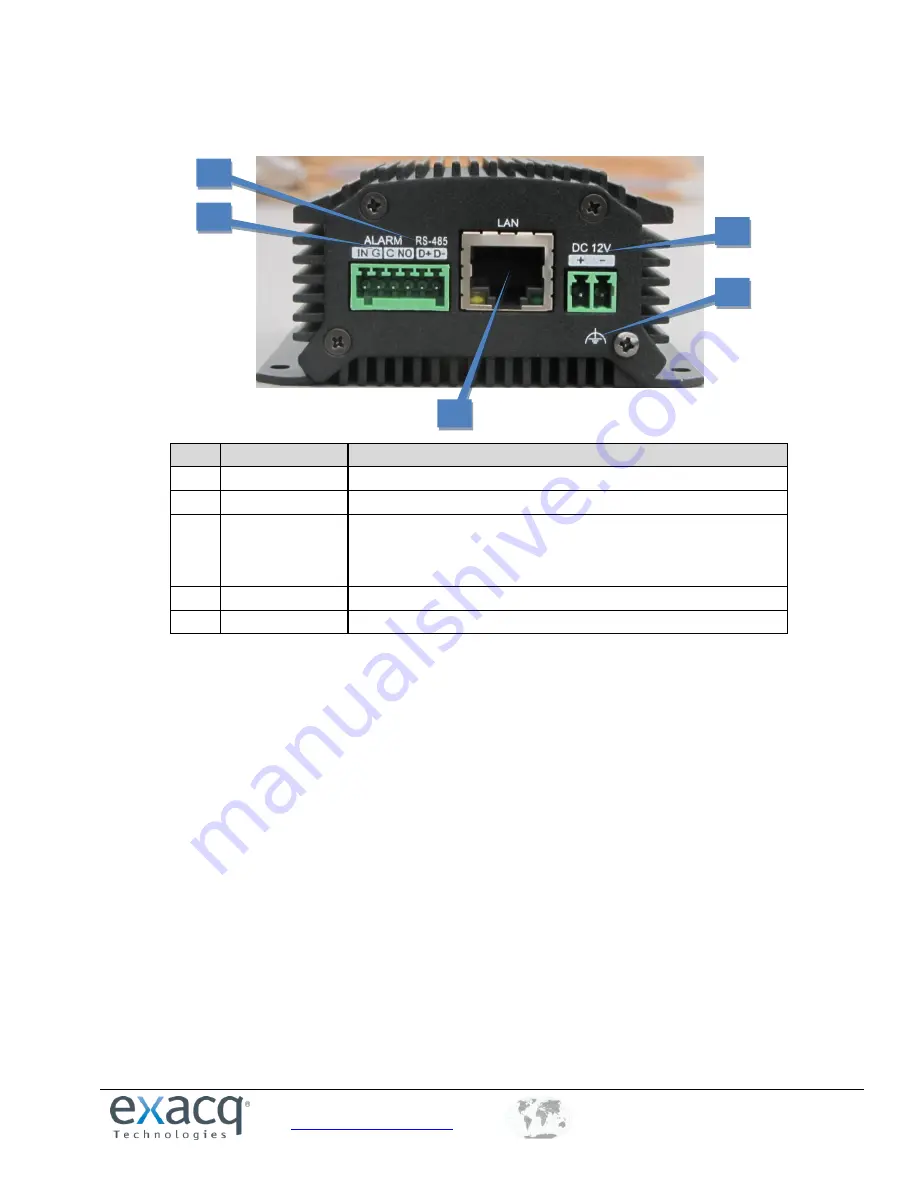
E-ADE1C REAR PANEL 


Item 

Description 

ALARM IN /OUT 

Relay alarm input/output. (JP2 pin not available on output.) 

RS-485 

RS-485 serial interface; connect to pan/tilt unit, speed dome, etc. 

LAN 

10M/100Mbps adaptive Ethernet interface (PoE). Right LED indicator 
lights in green when the network cable is connected; left LED 
indicator blinks in orange when data is transmitting/receiving.  

DC12V 

12V DC power supply.  

GND 

Grounding. 


1


2


3


4


5


Summary of Contents for exacqVision E Series

Page 1: ...mes or their products Exacq Technologies Inc disclaims any proprietary interest in trademarks and trade names other than its own Exacq Technologies makes no warranty of any kind with regard to this material including but not limited to the implied warranties of merchantability and fitness for a particular purpose Exacq Technologies shall not be liable for errors contained herein or for incidental ...

Page 2: ...www exacq com 1 317 845 5710 44 1438 310163 USA Corporate Headquarters Europe Middle East Asia 2 ...

Page 3: ...ng to an exacqVision System 14 Initiating the Connection 14 Verifying the Connection 15 5 Encoder Configuration Page 16 Installing Web Components 16 Main Page 18 6 Live View 19 Starting Live View 19 Capturing a Picture 20 Operating PTZ Controls 21 Configuring Video Parameters 24 7 Device Configuration 25 Local Configuration 25 Configuring Time Settings 26 8 Network Settings 27 Configuring TCP IP S...

Page 4: ...s Alarm 49 Configuring a Privacy Mask 50 Configuring Video Tampering 51 Configuring Text Overlay 52 Configuring Holiday Settings 53 10 RS 232 and RS 485 Settings 54 Configuring RS 232 54 Configuring RS 485 Settings 55 11 Alarm Input Output 56 Configuring the External Alarm Input 56 Configuring the External Alarm Output 58 12 Exceptions 59 13 User Management 60 Adding a User 61 Modifying a User 62 ...

Page 5: ...ome and Safari Remote web browser access by HTTPS ensuring high security Netfilter builds internet firewalls based on packet filtering QoS protocol enhances the data transmission performance Supports SNMPv1 v2c v3 simple network management protocol mDNS based Apple s Bonjour protocol which enables automatic discovery of devices Zero configuration networking Zeroconfig which automatically obtains t...

Page 6: ...ption alarm handling includes network disconnect alarm IP address conflict alarm illegal access alarm and more multiple alarm handling methods supported relay alarm output buzzer alarm and more Exception reboot software watchdog for inspecting important threads and system resources of device device automatically restarted if exceptions are detected Firmware watchdog for inspecting the firmware of ...

Page 7: ... card is inserted 2 VIDEO IN BNC connector for video input 3 LINE IN 3 5mm interface for two way audio input or audio input connect to audio input device or active pick up microphone etc 4 AUDIO OUT 3 5mm interface connect to audio output device such as loudspeaker 5 microSD microSD interface for log storage 6 RESET Hold button for more than 15 seconds after power is turned on to restore factory d...

Page 8: ...D Indicator Red when the device is powered on orange when the SD card is inserted 2 LINE IN 3 5mm two way audio input interface connect to active pick up microphone etc 3 AUDIO OUT 3 5mm interface connect to audio output device such as loudspeaker 4 VIDEO IN BNC interface for video input 5 AUDIO IN Line input interface for audio input 1 2 3 4 5 ...

Page 9: ...put output JP2 pin not available on output 2 RS 485 RS 485 serial interface connect to pan tilt unit speed dome etc 3 LAN 10M 100Mbps adaptive Ethernet interface PoE Right LED indicator lights in green when the network cable is connected left LED indicator blinks in orange when data is transmitting receiving 4 DC12V 12V DC power supply 5 GND Grounding 1 2 3 4 5 ...

Page 10: ...nnel 4 RS 485 RS 485 serial interface connect to pan tilt unit speed dome etc 5 RESET Hold button for more than 15 seconds after the device is turned on to restore factory default settings 6 microSD microSD interface for data storage 7 LAN 10M 100Mbps adaptive Ethernet interface PoE Right LED indicator lights in green when the network cable is connected left LED indicator blinks in orange when dat...

Page 11: ...s the open close relay input as the alarm output mode The alarm input can be selected to NO or NC Different alarm output connection methods are applied to the AC or DC load NOTE The one input encoder does not have a JJ1 relay Please note the different connections of JJ1 shown here For DC load JJ1can be safely used both in NC and NO modes and it is recommended within the limit of 12V 1A For externa...

Page 12: ...address In either case you can use the E Series IP utility to find and configure the IP address and other network parameters Searching Online Devices Click to run the IP utility It automatically searches online devices every 15 seconds on the computer s subnet It displays the total number of located devices in the Online Devices interface Device information such as device type IP address port numb...

Page 13: ...parameters of multiple devices simultaneously select all the devices to be modified before editing the parameters The IP address entered is incremented by one for the additional selected devices that is if you enter 10 13 6 43 for the first selected device the next device will be assigned 10 13 6 44 and so on until each selected device is assigned an address Restoring Default Password It is recomm...

Page 14: ...ras 3 Click Rescan Network to ensure all cameras and encoders are displayed in the Find IP Cameras list 4 Locate the encoder in the Find IP Cameras list 4a To narrow the list type information about the encoder such as E Series or the IP address in the search box 4b 5 Select the encoder entry in the list to display the encoder in the IP Camera Information section 5a Enter the username and password ...

Page 15: ...e exacqVision Client live page 2 Expand the server in the site tree 3 Select an encoder channel combination to display video from the camera in the playback window 4 If audio is connected drag an audio channel into the playback window to verify the audio connection and transmission For complete information about exacqVision Client click the Help button or download the user manual from https exacq ...

Page 16: ...er Chrome 8 and later Safari 5 0 2 and later Windows XP SP1 and later 32 bit You will need the following for access to the encoder s web configuration page The network settings of device as configured in the Network Parameters chapter of this document A connection to the LAN for the encoder and a client computer The username of the encoder default admin and its password default admin256 Installing...

Page 17: ...ord default admin256 and then click Login 3 Download and install the plug in if prompted 4 Click on the live view panel by following the onscreen prompts 5 Click Run or Save on the pop up warning message box 6 Click Next on the pop up Setup dialog box 7 When the installation completes click Finish to complete the installation of Web Components ...

Page 18: ... Live Video Window Display the live video of the current camera 4 Window division Choose a Live View display mode 5 Toolbar Control functions in live view mode such as live view audio on off two way audio and more 6 PTZ Control Control pan tilt zoom and the lighter and wiper controls 7 Preset Setting Calling Set and call the preset for the camera supports PTZ functions 8 Video Parameters menu Conf...

Page 19: ...ve View Live View shows you the video image transmitted from the connected camera in real time After successful login the system will open Live View automatically Starting Live View 1 In the Live View window select a video window 2 Double click a camera from the device list to start the Live View 1 2 3 ...

Page 20: ...vious page Next page Audio on off Start stop two way audio Stream Type must be configured TIP To display full screen mode double click a live video window To switch to the previously selected mode double click the live video window again Capturing a Picture Click the button on the toolbar to capture live pictures in JPEG format When the picture is captured the following pop up message box will app...

Page 21: ...at supports PTZ functions Connect the R and R terminals of the device to RS 485 D and RS 485 D terminals of the encoder 2 The baud rate PTZ control and address are configured in the RS 485 Settings interface on the Remote Configuration menu select Serial Port Settings and then 485 Serial Port The PTZ controls contain eight directional buttons up down left right upper left upper right bottom left b...

Page 22: ...ht Wiper Adjust speed of pan tilt movement To configure presets complete the following steps 1 In live view mode select a preset number from the preset list 2 Use the PTZ control buttons to point the camera in the desired direction with the desired settings You can use any of the following commands 3 Click the icon to set the preset Up to 256 presets are configurable depending on the PTZ protocol ...

Page 23: ...438 310163 USA Corporate Headquarters Europe Middle East Asia 23 To call a preset in Live View mode select a predefined preset from the list and click the icon The preset can also be used to link to the alarm input when an alarm occurs ...

Page 24: ...itions Four modes are selectable Standard Use for general lighting conditions default Indoor The image is relatively smoother Outdoor The image is relatively clearer and sharper The degree of contrast and saturation is high Dim Light The image is smoother than the other three modes 3 Move the slider to set the brightness contrast saturation and hue from 0 to 255 The default value is 128 for the br...

Page 25: ...very of streaming data and higher video quality but with slightly slower transmission 3 Stream Type Select the web browser s live video stream type Main Stream or Sub Stream See Configuring Video Settings in this manualError Reference source not found for more information 4 Image Size Select the window division view mode 4 3 16 9 or Auto fill 5 Record File Size Select the size of packed video file...

Page 26: ... you select this option enter the NTP server s IP address port and frequency of synchronization from 1 to 10 080 minutes NOTE If the device is connected to a public network you should use a NTP server that has a time synchronization function such as the server at the National Time Center IP Address 210 72 145 44 If the device is in a customized network NTP software can be used to establish an NTP ...

Page 27: ...rface 2 Configure the NIC settings including the NIC Type IPv4 Address IPv4 Subnet Mask IPv4 Default Gateway and MTU settings 500 to 1500 3 If the DHCP server is available select DHCP to automatically obtain an IP address and other network settings from that server 4 If the DNS server settings are required for some applications configure the Preferred DNS Server and Alternate DNS Sever here 5 Clic...

Page 28: ...P download the SNMP software By setting the Trap Address the device can send the alarm event and exception messages to the surveillance center 2 From the Remote Configuration menu select Network Settings and then SNMP to enter the SNMP settings interface 3 Select SNMP v1 or SNMP v2c You can enable both SNMP v1 and SNMP v2c 4 Configure the Read SNMP community default public 5 Configure the Write SN...

Page 29: ...vel to auth priv auth no priv or no auth no priv 11 If the security level is set to auth priv you can configure the Authentication Algorithm and Private key Algorithm parameters If the security level is set to no auth no priv you cannot configure the Authentication Algorithm and Private key Algorithm parameters 12 Set the SNMP port default 161 13 Click Save to save the settings 8 9 10 11 12 13 ...

Page 30: ...uring Port Settings 1 From the Remote Configuration menu select Network Settings and then Port to open the Port Settings interface 2 Set the HTTP port default 80 RTSP port 554 and HTTPS port 443 of the camera 3 Click Save to save the settings A system restart is required to activate changed settings 1 2 3 ...

Page 31: ...otocol over Ethernet PPPoE is also available 1 From the Remote Configuration menu select Network Settings and then PPPoE Settings to open the PPPoE settings interface 2 Select the Enable PPPoE checkbox 3 Enter the User Name Password and Confirm Password for PPPoE access These must be assigned by the ISP 4 Click the Save button to save and exit 2 3 4 1 ...

Page 32: ...fferent DSCP values which identify different priority levels of data sending 1 From the Remote Configuration menu select Network Settings and then QoS to open the QoS settings interface 2 Select the Enable QoS checkbox 3 Enter the DSCP Differentiated Services Codepoint value for the video audio event alarm and management traffic This value is used to mark the traffic s IP header The DSCP value def...

Page 33: ...y access a server 1 From the Remote Configuration menu select Network Settings and then SOCKS to open the SOCKS Settings interface 2 Select the Enable SOCKS checkbox 3 Configure the following settings Server Enter the address of the SOCKS server Server Port Enter the port of the SOCKS server default 1080 Server Type Select the server type SOCKS4 or SOCKS5 If you select SOCKS5 you can enable the us...

Page 34: ...r to which your device is connected When the network working mode of the device is set as multi address the Default Route of the device should be in the same network segment as that of the LAN IP address of the router 1 From the Remote Configuration menu select Network Settings and then NAT to open the NAT settings interface 2 Select the Enable UPnP TM checkbox 3 Select the Port Mapping Mode Auto ...

Page 35: ...www exacq com 1 317 845 5710 44 1438 310163 USA Corporate Headquarters Europe Middle East Asia 35 6 You can view the status of the port mapping in the Port Status area 6 2 ...

Page 36: ...f the web site and associated web server that one is communicating with and create a secure channel over an insecure network HTTPS URLs begin with https and use port 443 by default 1 From the Remote Configuration menu select Network Settings and then HTTPS to open the HTTPS settings interface 2 Click Create to create the self signed certificate or authorized certificate This opens the following wi...

Page 37: ...ity for signature After receiving the signed valid certificate import the certificate to the device 4 After you have successfully created and installed the certificate select the Enable HTTPS checkbox After the HTTPS feature is enabled the system will use the HTTPS login mode by default when you input the IP address such as https 192 0 0 64 You can also input http IP address index asp such as http...

Page 38: ...his protocol Make sure you have installed the Bonjour plug in on your PC before enabling the Bonjour function 1 From the Remote Configuration menu select Network Settings and then Bonjour to open the Bonjour settings interface 2 Select the Enable Bonjour checkbox 3 Edit the name of device The name is shown when the device is detected by the system Only letters numbers and hyphens can be contained ...

Page 39: ...IP address can be added to the list allowed forbidden by Web Browser 1 From the Remote Configuration menu select Network Settings and then IP Address Filter to open the IP address filter settings interface 2 Select the Enable IP Address Filter checkbox 3 Select the filter type of IP address Allowed or Forbidden 4 Click the Add button to add the IP address to the selected filter type list 5 Click S...

Page 40: ...uthentication mechanism if using a LAN or WLAN 1 From the Remote Configuration menu select Network Settings and then 802 1x to open the IP address filter settings interface 2 Select the Enable IEEE 802 1X checkbox 3 The Protocol is automatically selected Select EAPOL Version 1 or 2 4 Enter the login credentials 5 Click Save to save the settings 1 2 2 3 2 4 2 5 2 ...

Page 41: ...Advanced Settings The Advanced page allows you to configure an alarm host 1 From the Remote Configuration menu select Network Settings and then Advanced to enter the Advanced interface 2 Enter the IP address and port of the alarm host 3 Select Enable Telnet if required 4 Click Save to save the settings 1 2 3 4 ...

Page 42: ...anged using exacqVision Client Configuring Display Settings To configure onscreen display complete the following steps 1 On the Remote Configuration menu select Camera Settings and then Display Settings to open the Display Settings interface 2 Select the camera from the Channel No drop down list 3 Edit the camera name in the Camera Name field 4 Select the display of camera name date or week by sel...

Page 43: ... In the preview image you can adjust the OSD location on the screen by moving the text frame 7 To copy the display settings of the current camera to other cameras expand the Copy to Camera panel and select the cameras or click Select All to select all cameras 8 Click Save to activate the settings 6 2 ...

Page 44: ...o type Video Stream or Video Audio The audio signal will be recorded only when the Video Type is Video Audio 7 Select the Resolution of the video input 8 Select the Bitrate Type Constant or Variable 9 If the bitrate is Variable select the Video Quality Up to six levels of video quality can be configured 10 Set the Frame Rate from 1 to 30 fps or 1 to 15 fps if Video Encoding is set to MJPEG 11 Set ...

Page 45: ...on is observed in the camera view To configure motion detection complete the following steps Set the Motion Detection Area 1 From the Remote Configuration menu select Camera Settings and then Motion Detection to open the Motion Detection settings interface 2 Select the Channel from the drop down list 3 Select the Enable Motion Detection checkbox 4 Click the Draw Area button 1 2 2 2 3 2 4 2 ...

Page 46: ...gging the mouse in the live video image Up to eight motion detection areas can be drawn in the same image 6 Click the Stop Drawing button to finish drawing 7 Click the Clear All button if you want to clear all areas 8 Move the Sensitivity slider bar to set the sensitivity of the camera 9 Click the Save button to save the settings 5 2 6 2 7 2 8 2 9 2 ...

Page 47: ...ach segment cannot be overlapped Up to eight segments can be configured for each day The Holiday option is available in the Schedule drop down list after you have enabled a holiday schedule in Holiday settings 3 Choose the day you for which want to set the arming schedule 4 Click the clock buttons to set the time period for the arming schedule 5 Copy the schedule to other days if desired 6 Click t...

Page 48: ...t the Alarm Actions Taken for Motion Detection 1 To specify the alarm type when an event is triggered select the Linkage Method tab 2 Select the alarming linkage methods Full Screen Monitoring Audible Warning Notify Surveillance Center 3 Select the Alarm Output to trigger 4 Select the Trigger Channel ...

Page 49: ...ngs and then Video Loss to open the video loss alarm setting interface 2 Select the Channel for which to configure the video loss alarm 3 Select Enable Video Loss Detection checkbox 4 Click Edit to edit the arming schedule for video loss detection The arming schedule configuration is the same as setting of the Arming Schedule for Motion Detection 5 Click the Linkage Method tab to set the actions t...

Page 50: ...amera Settings and then Privacy Mask to open the Privacy Mask settings interface 2 Select the Channel for which to configure the privacy mask 3 Select the Enable Privacy Mask checkbox 4 Click the Draw Area button not shown 5 Draw the mask area by clicking and dragging the mouse in the live video image Up to four privacy mask areas can be configured 6 Click the Stop Drawing button to finish drawing...

Page 51: ... Tampering interface 2 Select the Channel for which to configure the tamper proof detection alarm 3 Select the Enable Video Tampering checkbox 4 Draw the tampering area 5 On the Arming Schedule tab Click Edit to edit the arming schedule for tampering The arming schedule configuration is the same as for the Arming Schedule for Motion Detection 6 Select the Linkage Method tab to set the actions take...

Page 52: ...rlay Settings interface 2 Select the Channel from the drop down list 3 Edit the user defined text content 4 Select the checkbox to display the text in the overlay 5 In the preview image you can adjust the text location on the screen by moving the text frame 6 To copy the text overlay settings of the current camera to other cameras expand the Copy to Camera panel and select the cameras or click Sel...

Page 53: ...st and click the pencil button to edit the holiday 3 Edit the holiday name 4 Select the checkbox to enable the holiday s schedule 5 Select the time interval By Date By Week or By Month 6 Set the Start Date and End Date 7 Click OK to save the settings and go back to the Holiday Settings interface 8 Verify the finished holiday settings on the list 9 Repeat the same steps to configure up to 32 holida...

Page 54: ...te Configuration menu select Serial Port Settings and then 232 Serial Port to enter the RS 232 port setting interface NOTE If you want to connect the encoder by the RS 232 port the parameters of the RS 232 should be exactly the same as the parameters you configured here 2 Select the Baud Rate 3 Select the Data Bit 4 Select the Stop Bit 5 Select the Parity 6 Select the Flow Ctrl 7 Select the Usage ...

Page 55: ...om the Remote Configuration menu select Serial Port Settings and then 485 Serial Port to open the RS 485 port setting interface 2 Set the RS 485 parameters By default the Baud Rate is set as 9600 the Data Bit as 8 the Stop Bit as 1 and the Parity and Flow Ctrl as None The Baud Rate PTZ Protocol and PTZ Address parameters should be exactly the same as the parameters of the connected PTZ camera 3 Cl...

Page 56: ...nal Alarm Input To configure the external alarm input complete the following steps 1 From the Remote Configuration menu select Alarm Settings and then Alarm Input to open the Alarm Settings interface 2 Choose the Alarm Input No and the Alarm Type NO Normally Open or NC Normally Closed 3 Set the Arming Schedule for the alarm input 2 2 3 2 1 2 ...

Page 57: ... Screen Monitoring Audible Warning and Notify Surveillance Center 5 You can also choose the PTZ linking for the alarm input if your camera is installed with a pan tilt unit Choose the PTZ Linking channel and then select the Enable checkbox next to Preset Calling Patrol Calling or Pattern Calling 6 You can copy your settings to other alarm inputs 7 Click Save to activate the settings 4 2 5 2 6 2 7 ...

Page 58: ...s interface 2 Select one alarm output channel in the Alarm Output drop down list 3 Set the Delay time to 5sec 10sec 30sec 1min 2min 5min 10min or Manual The Delay refers to the time duration that the alarm output remains in effect after alarm occurs If you choose Manual you need to manually disable the alarm output 4 Click Edit to enter the Edit Schedule Time interface The time schedule configurat...

Page 59: ... When the selected resolution under Configuration Camera Settings Video Settings and the actual video input resolution are mismatched the exception alarm will occur To configure exceptions complete the following steps 1 From the Remote Configuration menu select Exceptions to open the Exception settings interface 2 Select the checkbox to set the action or actions Audible Warning or Notify Surveilla...

Page 60: ...10 44 1438 310163 USA Corporate Headquarters Europe Middle East Asia 60 13User Management The admin user can create up to 31 users From the Remote Configuration menu select User Management to open the User Information interface ...

Page 61: ...Search and Two way Audio in Configuration and all operating permission in Camera Configuration User Local Log Search in Local Configuration Remote Log Search in Configuration and only the local remote playback in the Camera Configuration 4 On the Basic Permission tab select Local Configuration and Remote Configuration permissions for the user 5 On the Camera Configuration tab select channels for w...

Page 62: ...62 Modifying a User To modify a user account an admin must complete the following steps 1 Select the user account from the list on the User Information interface 2 Click Modify to enter the setting interface 3 Modify the information as needed 4 Click OK to finish the user modification 1 2 2 2 4 2 ...

Page 63: ...ope Middle East Asia 63 Deleting a User To delete a user account complete the following steps 1 Select the user account from the list in the User Information interface 2 Click Delete to display a confirmation message 3 Click OK to delete the selected user account 1 2 2 2 3 2 ...

Page 64: ... be used only if the encoder has a microSD card installed To search the log complete the following steps 1 Click Log on the menu bar to enter the Log interface 2 Set the log search conditions to refine your search including the Major Type Minor Type Start Time and End Time 3 Click the Search button to start searching log files 4 Up to 100 matched log files are displayed in the list 5 You can click...

Page 65: ...emote Configuration menu select Device Parameters and then Device Information to open the Device Information interface You can edit the Device Name and Device No and view the device information including Model Serial No Firmware Version Encoding Version Number of Channels Number of HDDs Number of Alarm Input and Number of Alarm Output ...

Page 66: ...orporate Headquarters Europe Middle East Asia 66 Maintenance From the Remote Configuration menu select Maintenance to open the Maintenance interface Restarting the Device On the Maintenance page select Reboot Confirm the message to reboot the encoder ...

Page 67: ...iles of the device can be exported to a local device for backup and the configuration files of one device can be imported to multiple device devices if they are to be configured with the same parameters On the Maintenance page click Browse to select the file from the selected backup device and then click the Import button to import a configuration file After the import the device will reboot autom...

Page 68: ...ing support When you need help with your exacqVision product please be ready with a complete description of the problem including any error messages or instructions on re creating the error Technical support can be contacted as follows Exacq Technologies Inc 11955 Exit Five Parkway Bldg 3 Fishers IN 46037 USA Phone 1 317 845 5710 Fax 1 317 845 5720 e mail support exacq com Web http www exacq com ...

Page 69: ...sers are encouraged to try to correct the interference by one or more of the following measures Reorient the television or radio receiving antenna and or relocate the Exacq product and the radio or TV with respect to each other If necessary users should consult the manufacturer or an experienced radio television technician for additional suggestions Users may find helpful the following booklet pre...

Page 70: ...ED WARRANTIES OF MERCHANTABILITY FITNESS FOR A PARTICULAR PURPOSE TITLE OR NON INFRINGEMENT OR ANY OTHER WARRANTIES THAT MAY ARISE FROM USAGE OF TRADE OR COURSE OF DEALING EXACQ DOES NOT WARRANT GUARANTEE OR MAKE ANY REPRESENTATIONS REGARDING THE USE OF OR THE RESULTS OF THE USE OF THE PRODUCTS IN TERMS OF CORRECTNESS ACCURACY RELIABILITY OR OTHERWISE AND DOES NOT WARRANT THAT THE OPERATION OF THE...

Reviews: