Machine control – Operating elements
Machine display
22
099-00T500-EW501
2.9.2022
Item Symbol Description
0
20
I
2
Signal light for secondary current
4.2 Machine display
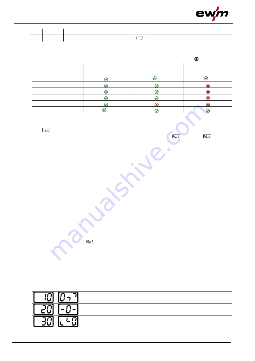
The following welding parameters can be displayed before (nominal values), during (actual values) or af-
ter welding (hold values). The display of the hold values is indicated by the signal light :
Parameter
Before welding
(nominal values)
During welding
(actual values)
After welding
(hold values)
Welding current
[2]
[3]
Parameter times
Parameter currents
Frequency, balance
JOB number
Welding voltage
[1]
[1]
not for MMA welding
[2]
The actual value display of the welding current for MMA can be switched on or off with the parame-
ter
.
[3]
The behaviour of the hold value display can be set with the parameters
for TIG and
for MMA.
The settings are made in the machine configuration menu
> see 5.11 chapter
.
The parameters that can be set in the machine control function sequence are dependent on the welding
task selected. This means that if no pulse variant was selected, for example, no pulse parameters will be
available to set in the function sequence.
4.3 Operating the machine control
4.3.1 Main screen
After switching on the machine or finishing a setting, the machine control changes to the main screen.
This means that the previously selected settings are accepted (if necessary, indicated by signal lights)
and the nominal value of the current (A) is shown in the welding data display on the left. The welding data
display on the right shows the nominal value for the preselected welding voltage (V). The control changes
back to the main screen after 4 s.
4.3.2 Setting the welding current (absolute/percentage)
The welding current is set with the control button (click wheel).
The welding current can be set as a percentage (of the main current) or an absolute value:
TIG:
Start, secondary and end current
MMA: Hot start current
To select, use the parameter
> see 5.11 chapter
in the configuration menu.
4.3.3 Welding parameter setting in the operation sequence
Set a welding parameter in the functional sequence by clicking (select) and turning the click wheel (navi-
gate to the desired parameter). Press again to apply the selected parameter as the setting (corresponding
parameter value and signal light flash). Then turn to set the parameter value.
During welding parameter setting, the parameter value to be set flashes in the left hand display. A para-
meter abbreviation or a deviation in the specified parameter value upwards or downwards is shown on
the right-hand display:
Display
Meaning
Increase the parameter value
To return to the factory settings.
Factory setting (example value = 20)
Parameter is set to optimum value
Decrease the parameter value
To return to the factory settings.


