Commissioning
Field bus connection and configuration
14
Item No.: 099-008225-EWM01
4.4
Field bus connection and configuration
Different steps are required for commissioning, depending on the field bus, and these steps are described
below.
4.4.1
Interbus-S optical fibre
No address setting is required for the configuration of the Interbus subscriber as this is given by the
position of the subscriber in the Interbus. The subscriber identifies with the ID3 as a module with digital
I/O.
4.4.1.1 Field bus connection
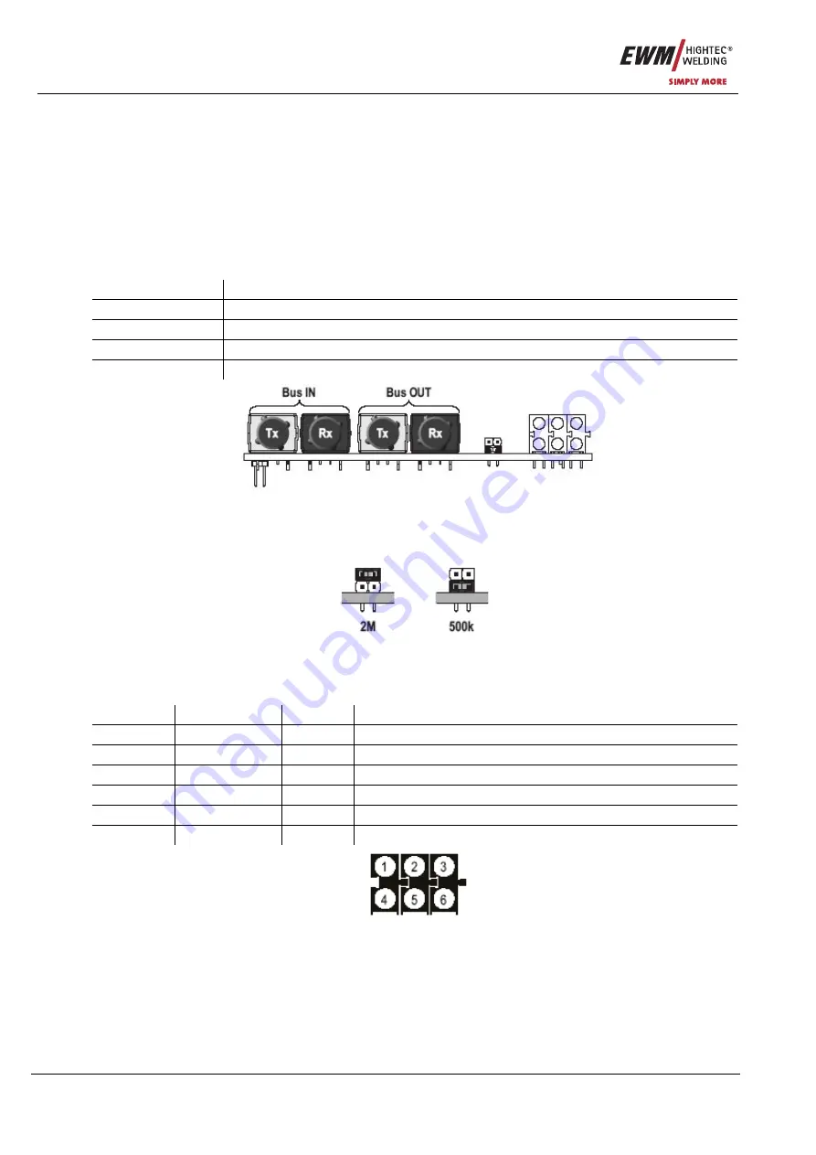
The field bus is connected via optical fibres using FSMA rapid-action connectors:
Plug Function
U7
Incoming interface, transmit line
U10
Incoming interface, receive line
U8
Outgoing interface, transmit line
U11
Outgoing interface, receive line
Figure 4-1
4.4.1.2 Baud rate
The module baud rate can be selected between 500kBaud and 2Mbaud using a jumper.
Figure 4-2
4.4.1.3 Status display
The status of the module on the Interbus is indicated as follows using a block of LEDs:
LED Signal Colour
Meaning
1
CC/RC
Green
Cable connection OK, master is not in reset status
2
BA
Green
Bus is in data exchange
3
RD
Yellow
Remote bus shut down
4
TR
Green
PCP communication active
5
FO1
Yellow
Warning for recipient of the bus input side
6
FO2
Yellow
Warning for recipient of the bus output side
Figure 4-3
4.4.1.4 Data capacity
The data capacity to be configured on the Interbus is based on the data profile being used. See also
chapter “Profiles for PHOENIX MIG/MAG systems”.


