7800R4X4-RF Switch Series
4X4 RF Router, Software Expandable to 8x16
Page 10
Revision 1.0
4.1.1. Inputs
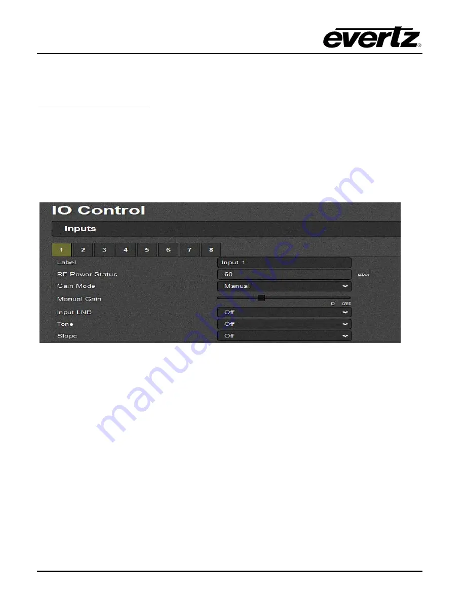
The RF Input control is used to monitor and edit transfer specifications of each individual input.
RF Input Control and Status
Label:
This field gets the name label of the corresponding input of XPRF.
RF Power Status: T
his field gets the input optical power. It displays “Off’ when value is -126 and
displays “Over” when value is 127.
Gain Mode:
This drop down allows the user to set the mode of gain control for XPRF input. Possible
options are Manual or AGC. This slide bar (Figure 4-5) allows the user to apply a fixed amount of gain
to the selected input. Available range is incremented or decremented in 1dB steps.
Figure
4-5 : WebEASY
®
- IO Control \ Manual Gain
Manual Gain:
In manual gain mode, the gain through the router for all outputs connected to a
particular input is fixed. The default value for all inputs is 0dB, with an adjustable gain range of
-10 to +20 dB.
If a high level input signal (i.e. -10 dBm) is set to full gain of +20 dB, the output level on any
connected inputs will be exceeding design limits. Significant distortion to the RF signal may
occur under these circumstances.
AGC Power:
AGC (Automatic Gain Control) the input through the system on a particular input is
fixed, to a user selected target output level (-20dBm is the default), with an adjustable range of
-40 to -10 dBm. The AGC maintains the output level if the input level is within the range
determined by the AGC output level and the available gain in AGC mode. Customer needs to
buy a license to enable the AGC mode.
Input LNB:
This field allows the user to set the LNB power to 13v, 18v or turn it Off.
Tone:
This field allows the user to enable or disable the 22KHz tone.
Slope:
This field allows the user to set the RF slope correction level.


