background image

7780M4-ASI / 7780D4-ASI 

Quad ASI TDM-Mux/Demux 

Page 16 

Revision 1.0


ASI Output Enable:  

Use the 

ASI Output Enable

 drop-down box to select if the ASI output 

should be enabled or disabled.  


7.2.2. Monitor 


Total TS Bit Rate:

 This field displays the total bit rate for the entire stream (including NULL 

packets). 


Null Packet Bit Rate:

 This field displays the current bitrate of the NULL packets. 


Useful Bit Rate:

 This field displays the actual bitrate in use (Total TS Bit Rate – Null Packet Bit 

Rate) and reflects the actual bit rate currently being used by this input. 


Number of Active PIDs:

 This field displays the number of PIDs detected in the stream. 


Number of Continuity Count Errors: 

This field displays the number of continuity counts that 

have been detected since the last “Reset Measurements” or reboot.  


"


Note: This is particularly useful during troubleshooting to determine if the 
packets are being dropped on the input. 


7.3. 

SDI IN TAB 

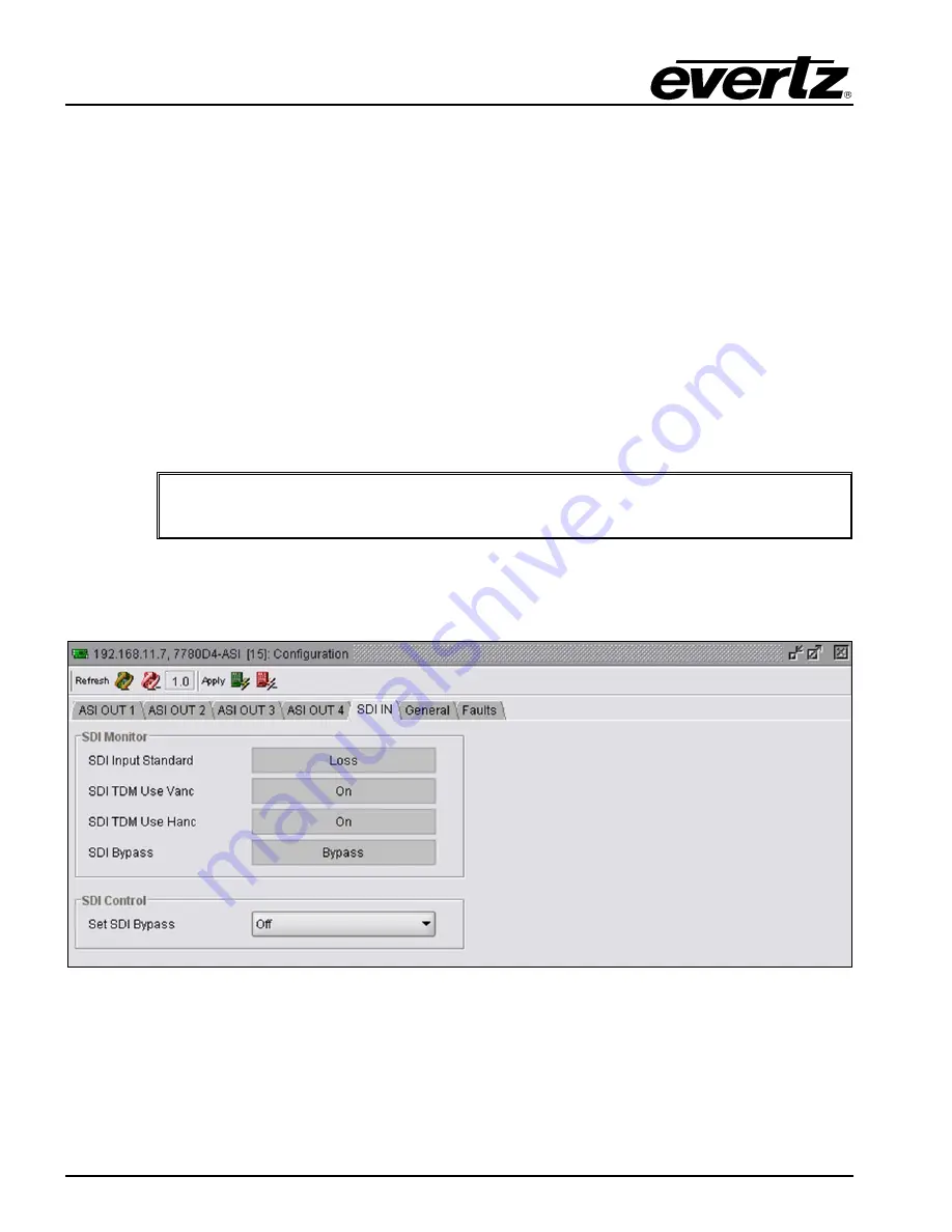
The 

SDI IN

 tab enables the user to monitor and set the SDI input information. 


Figure 7-2: SDI IN – 7780D4-ASI 


Summary of Contents for 7780D4-ASI

Page 1: ...CAL 6 3 5 COMPLIANCE 6 4 TECHNICAL SPECIFICATIONS 7780D4 ASI 7 4 1 ASI INPUT 7 4 2 OUTPUT 7 4 3 ELECTRICAL 7 4 4 PHYSICAL 7 5 VISTALINK REMOTE MONITORING CONTROL 8 5 1 WHAT IS VISTALINK 8 5 2 CONNECTING TO VLPRO 8 6 CARD CONFIGURATION 7780M4 ASI 10 6 1 CONFIGURING THE 7780M4 ASI USING VISTALINK 10 6 2 ASI IN 1 2 3 4 TABS 10 6 3 SDI OUT TAB 12 6 4 GENERAL TAB 13 6 5 FAULTS 14 7 CARD CONFIGURATION 7...

Page 2: ... ASI and 7780M4 ASI Rear Plates 3 Figure 2 2 Rear View of 7700FR Frame 5 Figure 2 3 VistaLINK PRO Hardware Configuration 9 Figure 3 1 ASI IN 1 7780M4 ASI 10 Figure 3 2 SDI OUT 7780M4 ASI 12 Figure 3 3 General 7780M4 ASI 13 Figure 3 4 Faults 7780M4 ASI 14 Figure 4 1 ASI OUT 1 7780D4 ASI 15 Figure 4 2 SDI IN 7780D4 ASI 16 Figure 4 3 General 7780D4 ASI 17 Figure 4 4 Faults Tab 7780D4 ASI 19 Figure 5 ...

Page 3: ...y warranty offered by Evertz in relation to this product is the Evertz standard limited warranty stated in the sales contract or order confirmation form Although every attempt has been made to accurately describe the features installation and operation of this product in this manual no warranty is granted nor liability assumed in relation to any errors or omissions unless specifically undertaken i...

Page 4: ...7780M4 ASI 7780D4 ASI Quad ASI TDM Mux Demux Page iv Revision 1 0 This page left intentionally blank ...

Page 5: ...y loss of any all DVB ASI input feeds Comprehensive signal and card status monitoring via four digit card edge display or remotely through SNMP and VistaLINK VistaLINK capability is available when modules are used with the 3RU 7700FR C frame and a 7700FC VistaLINK Frame Controller module in slot 1 of the frame Fully hot swappable from front of frame Output is a single 270Mb s signal compatible wit...

Page 6: ...put is user selectable from the four ASI outputs Comprehensive signal and card status monitoring via four digit card edge display or remotely through SNMP and VistaLINK VistaLINK capability is available when modules are used with the 3RU 7700FR C frame and a 7700FC VistaLINK Frame Controller module in slot 1 of the frame Occupies one card slot can be housed in a standalone frame a 1RU frame holdin...

Page 7: ...vides an illustration of the 7780M4 ASI and 7780D4 ASI rear plates Figure 2 1 7780D4 ASI and 7780M4 ASI Rear Plates 2 1 1 7780M4 ASI Connectors SDI Out This BNC connector with serial digital video output is compatible with SMPTE 259M This BNC carries out the compressed multiplexed content from outputs 1 2 3 and 4 The content from the SDI Output can only be demultiplexed using the 7780D4 ASI Loop O...

Page 8: ...al digital video input is compatible with SMPTE 259M compliant TDM streams as provided by the companion 7780M4 ASI The SDI Input connector receives a signal from the multiplexer 7780M4 ASI which is to be demultiplexed by the demultiplexor 7780D4 ASI Loop Out This BNC can be used to loop out any of the 4 ASI inputs It is mainly used for troubleshooting purposes ASI Output 1 2 3 4 These four BNC con...

Page 9: ... or 7780D4 ASI and separate the rear card from the main card Locate the blank plates on the rear of the rack and remove a single blanking panel Insert the rear plate into the back of the chassis and secure using the two screws provided Figure 2 2 Rear View of 7700FR Frame Before inserting the front card connect the serial cable to the board using the serial cable provided Now insert the 7780M4 ASI...

Page 10: ...SMPTE 259M C framing compatible Monitor DVB ASI output Total Active Bitrate 210Mb s Number 1 1 monitor Connector BNC per IEC 61169 8 Annex A Signal Level 800mV nominal DC Offset 0V 0 5V Rise and Fall Time 900ps nominal Overshoot 10 of amplitude Return Loss 15dB up to 270Mb s Wide Band Jitter 0 2UI 3 3 ELECTRICAL Voltage 12VDC Power 10W 3 4 PHYSICAL Number of slots 1 3 5 COMPLIANCE Electrical Safet...

Page 11: ...r equivalent cable Return Loss 15dB up to 270Mb s 4 2 OUTPUT Standard DVB ASI DVB TR 101 891 270 Number of Outputs 4 independent DVB ASI Monitor Output 1 output selectable from outputs 1 4 Connector BNC per IEC 61169 8 Annex A Signal Level 800mV nominal DC Offset 0V 0 5V Rise and Fall Time 900ps nominal Overshoot 10 of amplitude Return Loss 15dB up to 270Mb s Wide Band Jitter 0 2UI 4 3 ELECTRICAL ...

Page 12: ...nd control Evertz VistaLINK enabled products 2 Managed devices such as 7780M4 ASI and 7780D4 ASI cards each with a unique address OID communicate with the NMS through an SNMP Agent Evertz VistaLINK enabled 7700 series modules reside in the 3RU 7700FR C MultiFrame and communicate with the manager via the 7700FC VistaLINK frame controller module which serves as the Agent 3 A virtual database known a...

Page 13: ...ardware Configuration Please consult your network administrator if you have problems connecting the card with VLPro alternatively contact Evertz Microsystems Ltd or your authorized reseller for technical support Consult the VistaLINK Pro manual for instruction on how to use VistaLINK software ...

Page 14: ...is frame and should be named appropriately 7780M4 ASI followed by square brackets to indicate the slot number used 6 2 ASI IN 1 2 3 4 TABS Right click the card and select View Configuration from the context sensitive menu You will be presented first with the ASI IN 1 tab The following three tabs labeled ASI IN 2 ASI IN 3 ASI IN 4 have identical controls and layout but refer to each of the separate...

Page 15: ...ly disable an input in some situations use this drop down box to select if the input should be enabled or disabled Note ASI IN 1 should typically be enabled at all times Input 1 will auto detect the type of input as it can accept either ASI or SDI the other three ports only accept ASI When SDI is detected the other inputs are automatically disabled and the SDI bypasses onto the SDI line 6 2 2 Moni...

Page 16: ...Outputs Video Standard Options are N270 if you are running in an NTSC facility and P270 if you are running in a PAL facility Vanc Mapping The Vanc Mapping control allows the user to enable or disable the Vanc Mapping function The drop down menu options are Off or On Hanc Mapping The Hanc Mapping control allows the user to enable or disable the Hanc Mapping function The drop down menu options are O...

Page 17: ...oblems By default the password is set to 7154 In order to change your password type in the old 4 digit password followed by the new 4 digit password and then click on the Apply button 6 4 2 Monitor Output Bit Rate This shows the current maximum bitrate that the M4 is able to pass The maximum is dependant upon the settings on the SDI OUT tab as detailed below VANC HANC MAX Mb s OFF OFF 160 OFF ON 1...

Page 18: ... Trap Enable ASI Trap Status The ASI Trap Enable section allows the user to set which ASI Trap Enable controls are enabled The ASI Trap Status allows the user to monitor the status of the faults ASI Output 1 2 3 4 This status indicator will remain red unless a valid ASI output is present ASI Input Bandwidth 1 2 3 4 This trap status will change to red if the ASI input bandwidth exceeds the limit se...

Page 19: ... ASI OUT 1 2 3 4 Right click the card and select View Configuration from the context sensitive menu You will be presented at first with the ASI OUT 1 tab The following three tabs labeled ASI OUT 2 ASI OUT 3 ASI OUT 4 have identical controls and layout but refer to each of the separate outputs For the sake of brevity only ASI OUT 1 will be described in detail The configuration window in Figure 7 1 ...

Page 20: ...lays the actual bitrate in use Total TS Bit Rate Null Packet Bit Rate and reflects the actual bit rate currently being used by this input Number of Active PIDs This field displays the number of PIDs detected in the stream Number of Continuity Count Errors This field displays the number of continuity counts that have been detected since the last Reset Measurements or reboot Note This is particularl...

Page 21: ...ntrol Set SDI Bypass The Set SDI Bypass drop down menu enables the user to select the SDI Bypass mode In ON mode the module will operate like a DA where any stream present at the SDI input will be distributed to all four ASI outputs In OFF mode the SDI input will not be distributed to any of the ASI outputs the module will only operate as a demultiplexer In Auto mode if the content present at the ...

Page 22: ...nizations and over bandwidth usage could cause transmission problems NOTE By default the password is set to 7154 In order to change your password type in the old 4 digit password followed by the new 4 digit password then click on the Apply button 7 4 2 Monitor Used Link Bit Rate This field displays the actual incoming data bitrate Firmware Version This field displays the current firmware version o...

Page 23: ...u wish to enable Figure 7 4 Faults Tab 7780D4 ASI SDI Input This status indicator will remain green as long as a valid SDI input is detected ASI Output 1 2 3 4 This status indicator will remain red unless a valid ASI Output is present ASI Input Bandwidth 1 2 3 4 This trap status will change to red if the ASI input bandwidth exceeds the limit set by the user Input 1 2 3 4 Continuity Count Error Thi...

Page 24: ... use to provide access to all the latest features or enhancements It will also be necessary to add JAR files for new products If your new product has not appeared even after waiting a few minutes for the Ethernet switch negotiation to complete then it is possible that your JAR file may be old or missing To perform a JAR update ensure that all VLPro clients are closed those clients which are not cl...

Page 25: ...onfirm that all updates have been successfully applied by selecting from the menu Tools View Show Hide Product update log Shutdown the server by selecting from the menu File Shutdown Server Now re open the server it is normal for the start up to take marginally longer while each individual update is being applied Once complete you may restart the VLPro Clients As the Client restarts you will exper...

Page 26: ...igital Video Broadcasting baseline system for digital terrestrial television EN 300 744 9 EIT Event Information Table ETR ETSI Technical Report ETS European Telecommunication Standard FEC Forward Error Correction GOP Group of Pictures HEX Hexadecimal ISO International Organization for Standardization ITU International Telecommunication Union MGT Master Guide Table MPEG Moving Picture Experts Group...

Reviews: