background image


570DSK-25G Series 


Single Path Downstream Keyer with Logo Insertion 


User Manual 


© Copyright 2021 


EVERTZ MICROSYSTEMS LTD. 

5292 John Lucas Drive 

Burlington, Ontario  

Canada L7L 5Z9 


Phone: 

+1 905-335-3700 

Sales: 

[email protected] 

Fax: +1 905-335-3573 

Tech Support:  [email protected]  

Fax: +1 905-335-7571 

Web Page: 

http://www.evertz.com

     Twitter:      

@EvertzTV


Version 2.0, February 2021 


The material contained in this manual consists of information that is the property of Evertz Microsystems and is intended solely for the use of 

purchasers of the 570DSK Series Logo Inserter. Evertz Microsystems expressly prohibits the use of this manual for any purpose other than the 

operation of the 570DSK Series Logo Inserter. 


All rights reserved.  No part of this publication may be reproduced without the express written permission of Evertz Microsystems Ltd.  Copies 

of this manual can be ordered from your Evertz dealer or from Evertz Microsystems. 

Summary of Contents for 570DSK-25G Series

Page 1: ... 2021 The material contained in this manual consists of information that is the property of Evertz Microsystems and is intended solely for the use of purchasers of the 570DSK Series Logo Inserter Evertz Microsystems expressly prohibits the use of this manual for any purpose other than the operation of the 570DSK Series Logo Inserter All rights reserved No part of this publication may be reproduced...

Page 2: ...This page left intentionally blank ...

Page 3: ...rd grounding prong The wide blade or the third prong is provided for your safety If the provided plug does not fit into your outlet consult an electrician for replacement of the obsolete outlet Protect the power cord from being walked on or pinched particularly at plugs convenience receptacles and the point where they exit from the apparatus Only use attachments accessories specified by the manufa...

Page 4: ...ly to cause harmful interference in which case the user will be required to correct the interference at his own expense INFORMATION TO USERS IN THE U S A NOTE FCC CLASS A DIGITAL DEVICE OR PERIPHERAL This equipment has been tested and found to comply with the limits for a Class A digital device pursuant to Part 15 of the FCC Rules These limits are designed to provide reasonable protection against ...

Page 5: ...d The only warranty offered by Evertz in relation to this product is the Evertz standard limited warranty stated in the sales contract or order confirmation form Although every attempt has been made to accurately describe the features installation and operation of this product in this manual no warranty is granted nor liability assumed in relation to any errors or omissions unless specifically und...

Page 6: ...570DSK 3G 4K 25G Logo Inserter Page ii Revision 2 0 This page left intentionally blank ...

Page 7: ...EVICE CONFIG 15 3 4 PTP CONTROL 17 3 5 QSFP 19 3 6 CONTROL INTERACES 20 3 7 DATA INTERFACES 20 3 8 VIDEO INPUT STREAMS 21 3 9 VIDEO OUTPUT STREAMS 22 3 10 AUDIO INPUT STREAMS 23 3 11 AUDIO OUTPUT STREAMS 24 3 12 ANC INPUT STREAMS 25 3 13 ANC OUTPUT STREAMS 25 3 14 HOST CONFIGURATION AND IP ROUTES 26 3 15 NMOS 27 3 16 GPIO CONFIG 28 4 WEB INTERFACE 29 4 1 DEVICE STATUS 31 4 2 DEVICE CONFIG 32 4 3 P...

Page 8: ...istaLINK Pro Audio Output Streams 24 Figure 4 11 VistaLINK Pro ANC Input Streams 25 Figure 4 12 VistaLINK Pro ANC Output Streams 25 Figure 4 13 VistaLINK Pro Host Configuration and IP Routes 26 Figure 4 14 VistaLINK Pro NMOS 27 Figure 4 15 VistaLINK Pro GPIO Config 28 Figure 5 1 WebEASY Login Menu 29 Figure 5 2 WebEASY 570DSK 25G Main Menu 30 Figure 5 3 WebEASY Device Status 31 Figure 5 4 WebEASY ...

Page 9: ...interface and or third party automation system over IP The 570DSK 25G is VistaLINK capable offering remote monitoring control and configuration capabilities via Simple Network Management Protocol SNMP Features One 3G 4K UHD external keyer with external key and fill Video formats HD 3G Level A and 12G single essence Full 12 bit linear keyer with video fade in and fade out processing Insert static o...

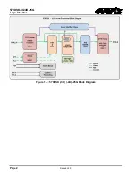
Page 10: ...570DSK 3G 4K 25G Logo Inserter Page 2 Revision 2 0 Figure 1 1 570DSK 3G 4K 25G Block Diagram ...

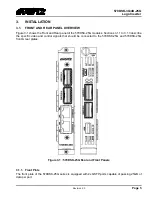
Page 11: ...ition Video Encapsulation SMPTE 2110 20 Audio Encapsulation SMPTE 2110 30 Metadata Encapsulation SMPTE 2110 40 2 2 REFERENCE SMPTE 2059 2 3 ETHERNET INTERFACE 4XQSFP28 2XRJ 45 10 100 1000 2 4 DATA FORMAT Ethernet IP UDP 2 5 PHYSICAL Number of Slots 1 2 6 ENCLOSURES 570FR 15 slot 3RU chassis Ordering Information 570DSK 25G 3G 4K UHD Single Downstream Keyer with Internal logo with Web and VistaLINK ...

Page 12: ...570DSK 3G 4K 25G Logo Inserter Page 4 Revision 2 0 Page left intentionally blank ...

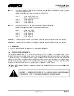
Page 13: ... the 570DSK 25G modules Sections 3 1 1 to 3 1 3 describe the specific video and control signals that should be connected to the 570DSK 25G and 570DSK 25G front rear plates Figure 3 1 570DSK 25G Rear and Front Panels 3 1 1 Front Plate The front plate of the 570DSK 25G series is equipped with 2x QSFP ports capable of passing 25GB of data per port ...

Page 14: ...review Lane 3 Input Not used Lane 4 Input Not used QSFP 2 This QSFP connector is the Backup Program Fill and Key input to the 570DSK 4K 3G 25G The Program Preview and HD Downconvert is also on the same connector Below is a breakdown of each of the lanes in the QSFP Lane 1 Input Program Fill Output Program HD Downconvert Lane 2 Input Key Output Preview Lane 3 Input Not used Lane 4 Input Not used 3 ...

Page 15: ...d a connection to the FTP Server 3 1 3 Reference PTP The 570DSK 25G can receive the PTP from QSFP interfaces 3 2 POWER REQUIREMENTS The standard 570DSK 25G is a 1 slot card contained within the 570FR The 570FR frame comes standard with one auto ranging power supply that automatically senses the input voltage over the range of 100 to 240 VAC An additional power supply 570PS can be ordered to provid...

Page 16: ...he 8 pin RJ 45 connector to carry Ethernet signals Even though pins 4 5 7 and 8 are not used it is mandatory that they be present in the cable 10BaseT and 100BaseT use the same pins a crossover cable made for one will also work with the other Pairs may be solid colors and not have a stripe Category 5 cable must use Category 5 rated connectors The maximum cable run between the downstream keyer and ...

Page 17: ...pplied with the 570FR frame is a multi colored ribbon cable with a six pin header socket on one end and a female 9 pin D connector on the other end Evertz part number WA S76 This cable is normally in the vinyl pouch at the front of the manual binder Connect the ribbon cable to port to J24 and power up the card Configure the port settings of the terminal program as follows Baud 115200 Parity no Dat...

Page 18: ...nserter Page 10 Revision 2 0 Figure 3 3 Tera Term Network Configuration To save the new IP address login again with root evertz and type reboot See Figure 3 4 below screenshot for reference Figure 3 4 Tera Term Saving New IP ...

Page 19: ...andard must be set manually to match the incoming video type see section 4 8 for VLPRO Configuration Common Name Pixels Active Lines Frame Rate Progressive Interlace Standard 1080i 50 1920 x 1080 25 I SMPTE 1080i 59 94 1920 x 1080 29 97 30 1 001 I SMPTE 720p50 1280 x 720 50 P SMPTE 720p59 94 1280 x 720 59 94 P SMPTE 1080p 50 1920 x 1080 50 P SMPTE 1080p 59 94 1920 x 1080 59 94 P SMPTE 4K 50 3840 x...

Page 20: ...570DSK 3G 4K 25G Logo Inserter Page 12 Revision 2 0 Page left intentionally blank ...

Page 21: ... the time to configure each module separately Finally VistaLINK enables the user to configure devices in the network from a central station and receive feedback that the configuration has been carried out There are 3 components of SNMP 1 An SNMP manager also known as a Network Management System NMS is a computer running special software that communicates with the devices in the network Evertz Vist...

Page 22: ...l operating range Good will be displayed Uptime This shows the amount of time that has elapse since the device was powered on The format is Days Hours Minutes Seconds FPGA Build Info Shows the FPGA version of the application running in the hardware System Time Shows the time of the hardware Operating Status Keyer Status Shows the status of the Keyer Logo Status Shows the status of the logo Licensi...

Page 23: ...570DSK 3G 4K 25G Logo Inserter Revision 2 0 Page 15 4 3 DEVICE CONFIG Figure 4 2 VistaLINK Pro Device Config ...

Page 24: ... server FTP Path Allows user to set the path where the logos are located in FTP server FTP User Allows user to set the username to access the FTP server FTP Pass Password Allows user to set the password to access the FTP server Logo Fade Duration Allows user to set the duration to fade in the logos HDC IP Address Allows user to set the ip address of the HDC hardware Video Loss Mode Allows user to ...

Page 25: ...riority 1 Allows the user to set the Priority 1 of the PTP Priority 2 Allows the user to set the Priority 2 of the PTP PTP Port Config Port 1 Port 2 Shows the main and backup PTP ports Interface Allows user to choose the interface where the PTP is receiving from Identity Shows the MAC address of the interface user selected State shows the state Slave or Listening of the PTP in DSK ...

Page 26: ...e Master Enable Allows the user to choose which PTP should be master By default settings should be off BMCA Transition Allows the user to view the BMC transition message PTP Status Current Steps Removed Allows the user to view the current steps removed Current Mean Path Delay Allows the user to view the path delay between delay request and delay response Parent Port Identity Allows the user to vie...

Page 27: ...570DSK 3G 4K 25G Logo Inserter Revision 2 0 Page 19 4 5 QSFP Figure 4 4 VistaLINK Pro QSFP QSFP sections shows the status and power levels of each QSFP lanes in each QSFP plugged in on DSK ...

Page 28: ... and view the IP address of each control interfaces Netmask Allows user to set and view the netmask of each control interfaces Reservation Allows user to set or view whether it is Static or DHCP MAC Address Allows the user to view the MAC address of each control interfaces Link Allows the user to view the link status of each control interfaces 4 7 DATA INTERFACES The Data Interface section shows t...

Page 29: ...he bandwidth of incoming data for the Port 4 8 VIDEO INPUT STREAMS The Video Input Stream section shows the details of each video input stream Figure 4 7 VistaLINK Pro Video Input Streams Input Stream Configurations Presence Allows user to view the status of each input streams indicating is there is a valid source detected or not Assignment Allows user to view the QSFP lanes where each ip input st...

Page 30: ...ce Ip address needs to be associated with multicast address Assignment Allows user to view the QSFP lanes where each ip output streams of DSK are transmitting to Source Port Allows user to set the source port Multicast Destination IP Allows user to set the multicast address for each DSK IP outputs Multicast Destination Port Allows user to set the multicast port for each DSK IP outputs Bandwidth Al...

Page 31: ...h stream supports 4 audio channels per multicast address Source IP Allows user to set the source ip address associated with the audio multicast address Multicast IP Allows user to set the multicast address for each stream Multicast Port Allows user to set the multicast port for each stream Presence Allows user to view the status of audio multicast address Channel Count Allows user to view the coun...

Page 32: ...t keep it Enabled Channel Count Allows user to configure how many audio channels can be transmitted per multicast address Source IP Allows user to set the source ip address to be associated with the audio multicast address Multicast IP Allows user to set the multicast address for each stream Multicast Port Allows user to set the multicast port for each stream Bandwidth Allows user to view the band...

Page 33: ...treams in program and program backup section Source IP Allows user to set the source ip address associated with the anc multicast address Multicast IP Allows user to set the multicast address for each stream Multicast Port Allows user to set the multicast port for each stream Presence Allows user to view the status of anc multicast address 4 13 ANC OUTPUT STREAMS Figure 4 12 VistaLINK Pro ANC Outp...

Page 34: ...t IP Allows user to set the multicast address for each stream Multicast Port Allows user to set the multicast port for each stream Status Allows user to view the status of the transmitting anc ip output stream 4 14 HOST CONFIGURATION AND IP ROUTES Figure 4 13 VistaLINK Pro Host Configuration and IP Routes Static Routes Allows user to set the static IP routes Default Gateway Allows user to set the ...

Page 35: ...icast DNS mode If it is set Unicast DNS mode user need to set Domain and Nameserver address to get device discovered in control system Domain Allows user to set the domain name of the unicast DNS server By default set local as domain name Nameserver Allows user to set the name server ip address of the DNS server By default set the nameserver ip address as 0 0 0 0 Priority Allows user to set the pr...

Page 36: ... 3G 4K 25G Logo Inserter Page 28 Revision 2 0 4 16 GPIO CONFIG Figure 4 15 VistaLINK Pro GPIO Config Control Panel Config The GPIO control enables the user to configure the General Purpose Inputs and Outputs ...

Page 37: ...or doing this simply type the IP address of the control port of 570DSK 25G module in the web browser Note Computer must be on the same subnet in order to have communication with the module If the module is in different subnet be sure to configure a gateway address to be able to access the module on a different subnet Figure 5 1 WebEASY Login Menu Login username and password is root evertz or admin...

Page 38: ...570DSK 3G 4K 25G Logo Inserter Page 30 Revision 2 0 Figure 5 2 WebEASY 570DSK 25G Main Menu ...

Page 39: ... This shows the amount of time that has elapse since the device was powered on The format is Days Hours Minutes Seconds FPGA Build Info Shows the FPGA version of the application running in the hardware System Time Shows the time of the hardware Operating Status Keyer Status Shows the status of the Keyer Logo Status Shows the status of the logo Licensing Device UID Shows the device s Unique ID whic...

Page 40: ...570DSK 3G 4K 25G Logo Inserter Page 32 Revision 2 0 5 2 DEVICE CONFIG Figure 5 4 WebEASY Device Config ...

Page 41: ...the logos are located in FTP server FTP User Allows user to set the username to access the FTP server FTP Pass Password Allows user to set the password to access the FTP server Logo Fade Duration Allows user to set the duration to fade in the logos Video Loss Mode Allows user to choose the video loss options Blue Screen Black Screen Frozen frame HDC Config HDC IP Address Allows user to set the ip ...

Page 42: ...nfig Domain Number Allow the user to set the domain number of the PTP Priority 1 Allows the user to set the Priority 1 of the PTP Priority 2 Allows the user to set the Priority 2 of the PTP PTP Port Config Port 1 Port 2 Shows the main and backup PTP ports Interface Allows user to choose the interface where the PTP is receiving from Identity Shows the MAC address of the interface user selected Stat...

Page 43: ...e Master Enable Allows the user to choose which PTP should be master By default settings should be off BMCA Transition Allows the user to view the BMC transition message PTP Status Current Steps Removed Allows the user to view the current steps removed Current Mean Path Delay Allows the user to view the path delay between delay request and delay response Parent Port Identity Allows the user to vie...

Page 44: ...36 Revision 2 0 5 4 QSFP Figure 5 6 WebEASY QSFP QSFP sections shows the status and power levels of each QSFP lanes in each QSFP plugged in on DSK 5 5 CONTROL INTERFACES The 1G Ethernet section shows the current status of each connection ...

Page 45: ...to set or view whether it is Static or DHCP MAC Address Allows the user to view the MAC address of each control interfaces Link Allows the user to view the link status of each control interfaces 5 6 DATA INTERFACES The 25G Ethernet section shows the current status of each connection Figure 5 8 WebEASY 25G Ethernet IP Address Allows user to view the IP address for each of the 25G lanes in QSFP Netm...

Page 46: ...STREAMS The Input Streams section shows the current status and details of each Input Stream Figure 5 9 WebEASY Input Streams Presence Allows user to view the status of each input streams indicating is there is a valid source detected or not Assignment Allows user to view the QSFP lanes where each ip input streams are receiving from Source IP Allows user to view the source IP address associated wit...

Page 47: ...ew the QSFP lanes where each ip output streams of DSK are transmitting to Source Port Allows user to set the source port Multicast Destination IP Allows user to set the multicast address for each DSK IP outputs Multicast Destination Port Allows user to set the multicast port for each DSK IP outputs Bandwidth Allows user to view the bandwidth of each DSK ip output streams in kbps 5 9 AUDIO INPUT ST...

Page 48: ...f audio channels present in audio multicast address Bandwidth Allows user to view the bandwidth of incoming audio stream 5 10 AUDIO OUTPUT STREAMS Figure 5 12 WebEASY Audio Output Streams The Audio Output Streams section shows the details of each Audio output stream Program and Preview Audio Outputs Allow user to configure main and backup of program and preview audio ip outputs Stream Each stream ...

Page 49: ...e pop suppression 5 11 ANC INPUT STREAMS Figure 5 13 WebEASY ANC Input Streams The ANC Input Streams section shows the details of each anc input stream Program Program Backup Allows user to configure the anc ip input streams in program and program backup section Source IP Allows user to set the source ip address associated with the anc multicast address Multicast IP Allows user to set the multicas...

Page 50: ...t address for each stream Multicast Port Allows user to set the multicast port for each stream Status Allows user to view the status of the transmitting anc ip output stream 5 13 HOST CONFIGURATION AND IP ROUTES Figure 5 15 WebEASY Host Configuration and IP Routes The host configuration and ip routes page allows the user to set of static ip routes default gateway and hostname of the device Static ...

Page 51: ...de If it is set Unicast DNS mode user need to set Domain and Nameserver address to get device discovered in control system Domain Allows user to set the domain name of the unicast DNS server By default set local as domain name Nameserver Allows user to set the name server ip address of the DNS server By default set the nameserver ip address as 0 0 0 0 Priority Allows user to set the priority of th...

Page 52: ...570DSK 3G 4K 25G Logo Inserter Page 44 Revision 2 0 5 15 GPIO CONFIG The GPIO control enables the user to configure the General Purpose Inputs and Outputs Figure 5 17 WebEASY GPIO Config ...

Page 53: ... there s a button labeled Upgrade The Upgrade button is used to check current firmware version and to upload the latest firmware Figure 6 1 Figure 6 1 WebEASY Upgrade Button on Top Menu Bar Clicking on the Upgrade button will take the user to Figure 6 2 where the current firmware version is shown Figure 6 2 WebEASY Firmware Upgrade Menu If the firmware version is outdated the user can upgrade by c...

Page 54: ...ically reboot The entire process can take more than 5 minutes Please be patient Note If you see any error messages generated by the browser just click wait After the card reboots log back into the webpage and verify the firmware was loaded correctly by clicking on the upgrade button and checking the listed firmware version If still the same firmware listed after the card rebooted then the upgrade ...

Page 55: ...ecifically frames 0 and 1 at the beginning of each minute except minutes 0 10 20 30 40 50 are omitted to compensate for an approximate timing error of 108 frames 3 seconds 18 frames per hour A flag bit is set in the time code to signal when the drop frame mode is in effect ITU The United Nations regulatory body governing all forms of communications ITU R previously CCIR regulates the radio frequen...

Page 56: ...d vertical interval time codes SMPTE 125M The SMPTE standard for bit parallel digital interface for component video signals SMPTE 125M defines the parameters required to generate and distribute component video signals on a parallel interface SMPTE 272M The SMPTE standard for embedding audio in serial digital standard definition SMPTE 259M C video signals SMPTE 274M The SMPTE standard for bit paral...

Reviews: