3405 Frame Manual
3405FR Series Fiber Optic SFP Frame
Revision 2.3
3405FR Series - 15
2.6.
FIBER INPUT AND OUTPUT CONNECTIONS
These connections are made using standard LC fiber connector ends on single mode fiber optic cable.
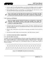
There are a total of 16 dual SFP slots. There can be a mix of 32 fiber inputs or outputs on the 3405FR
front panel. A high quality fiber optic cable such as Corning SMF-28 or suitable equivalents should be
used for optimum performance. Compatible SFP modules currently come in four configurations: dual
transmitters, dual receivers, reclocking transmitter, and reclocking receiver.
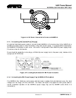
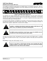
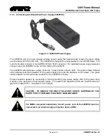
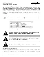
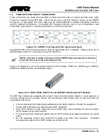
Figure 2-14: 3405FR Front View with Fiber Inputs and Outputs
Unpopulated SFP slots will remain inactive until the appropriate SFP is installed. Please ensure flat or
ultra flat polished fiber LC connectors are used for the SFPs.
NOTE: Channels A and B on the front of the 3405FR frame correspond to channels
A and B on the rear of the frame (Figure 2-16).
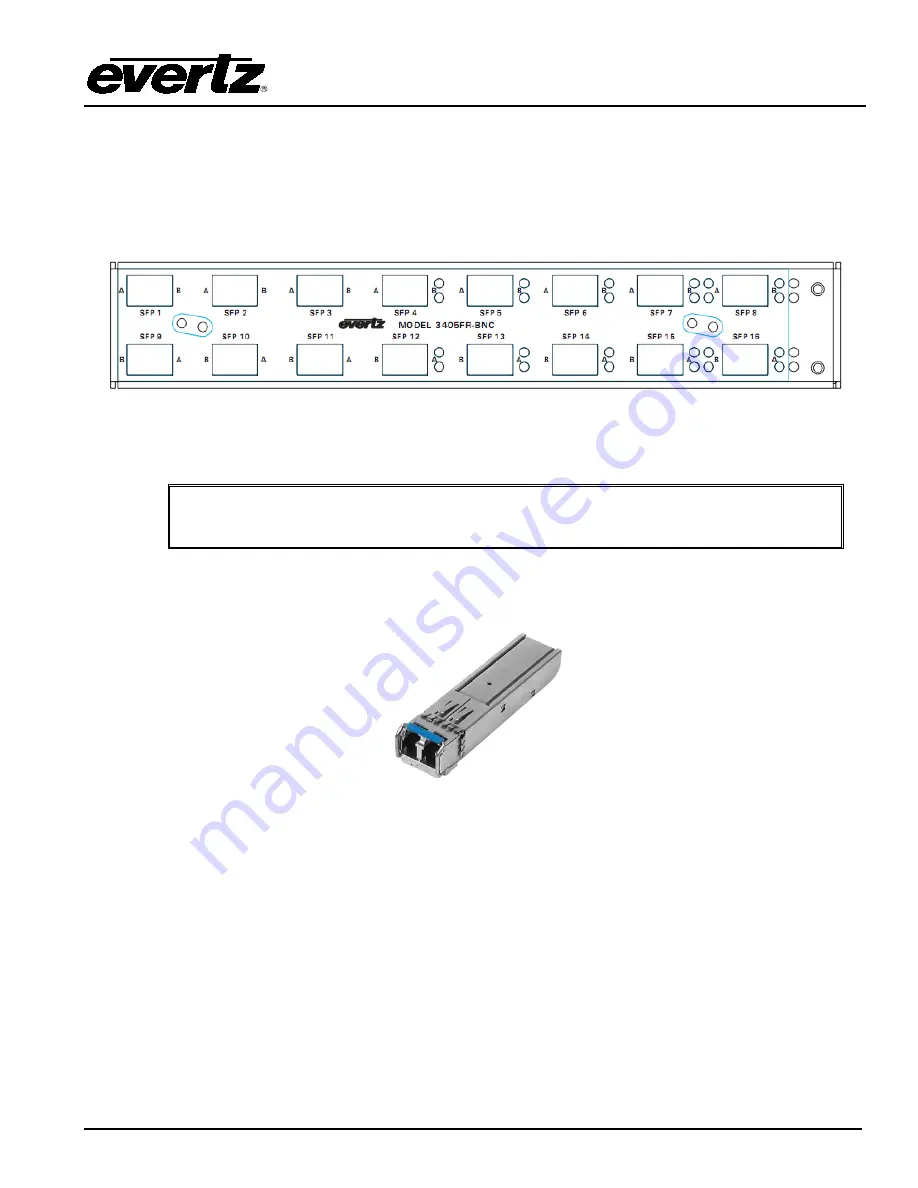
Figure 2-15 depicts any one of the following Evertz
®
SFP modules: 3405T13-2, 3405Txx/yy-2, 3405R-2,
3405R-2R, 3405OO13-DA4, and 3405OOxx-DA4.
Figure 2-15: 3405T, 3405R, 3405T13-R, and 3405OO13-DA4 Evertz
®
SFP Modules
The SFP fiber modules are equipped with a class 1 laser and emit invisible radiation. Avoid exposure to
the laser emitter and do not stare directly into unconnected SFP emitter ports or fiber ends that are
connected to SFP ports.
•
It is recommended that trained and qualified personnel install, replace or handle this equipment.
•
Ensure ESD precautions are followed during SFP installation.
•
Store SFP modules in static bags and wear an ESD strap when handling the optical modules.
SFP modules are also dust sensitive.
•
To prevent dust from entering the apertures of an SFP module, keep plugs inserted into the optical
bores.
•
Do not repeatedly remove and insert SFP modules more often than necessary. Repeated
removals and insertions of an SFP module can shorten its life.


