background image

EMR User's Guide 

High Density Modular Audio Router (AES, Analog, MADI, TimeCode, Data) 


Page 128 

Revision 1.8


CONFIGURATION 

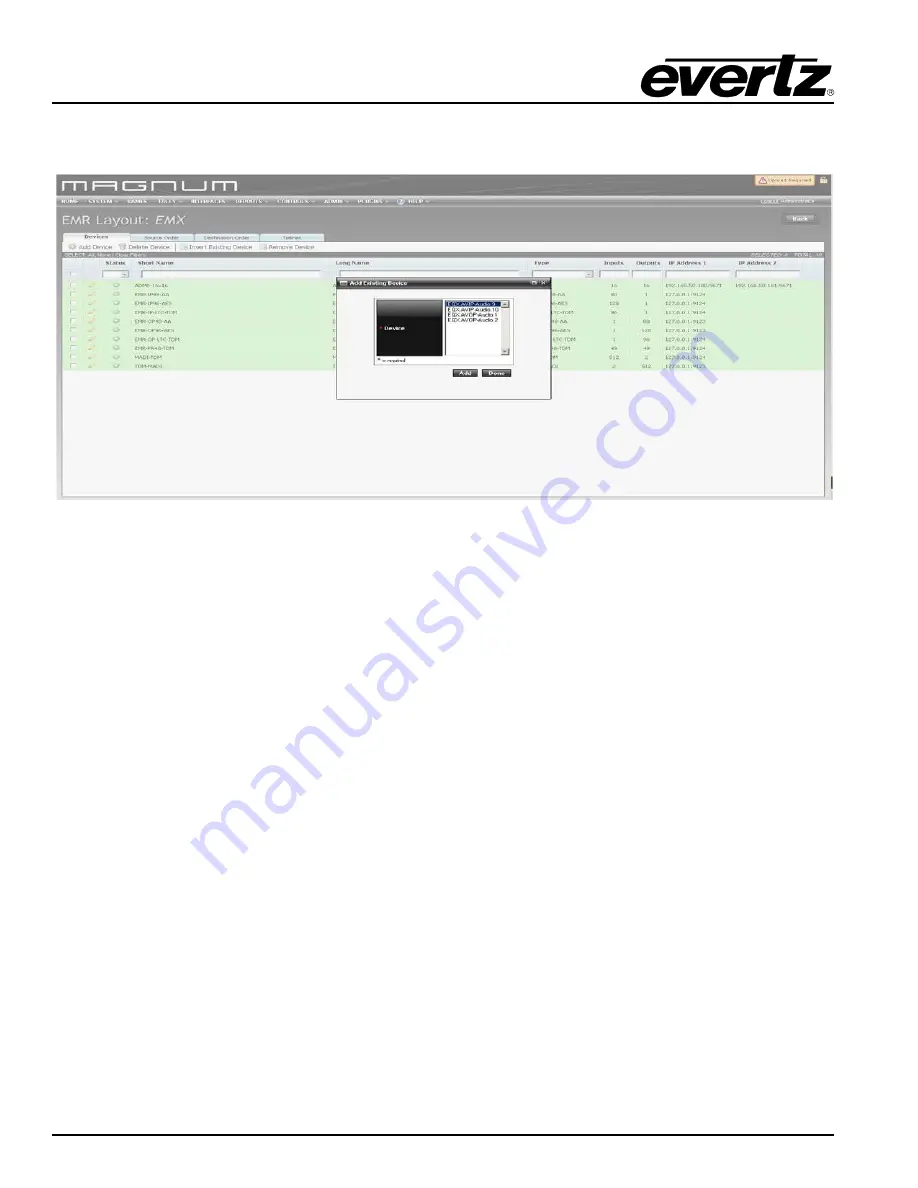
Once the AVIPs and AVOPs are defined edit the EMX frame and add these cards inside EMX frame by 
clicking on “Insert Existing Device”. Figure 6-5 shows an example of inserting AVIP under EMX frame. 


Figure 


6-5: Inserting Existing Device 


6.1.4.  Interfacing All EMR Audio Modules 

Once all of devices are added to Magnum, Tielines must be created to interface all of the modules.  As 
described earlier, each input module must connect to the ADMX-16X16/ADMX-48X48 via a TDM 
connection.  This TDM connection must be defined in the server so that the control system is aware of 
how to route the signal.  The connections are added using the 

Tielines

 page under the 

SYSTEM

 menu.   

 
A Tieline from each EMR input module, and each EQX de-embedder to the input of the ADMX must be 
created.  Also, a Tieline from the ADMX to each EMR output module and each EQX embedder must be 
created.  Figure 


6-6  shows an example of the Tielines that are created for an integrated audio routing 

system. 


Summary of Contents for 3000FR

Page 1: ...mation that is the property of Evertz Microsystems and is intended solely for the use of purchasers of the EMR Evertz Microsystems expressly prohibits the use of this manual for any purpose other than the operation of the EMR Due to ongoing research and development features and specifications in this manual are subject to change without notice All rights reserved No part of this publication may be...

Page 2: ...a third grounding prong The wide blade or third prong is provided for your safety If the plug provided does not fit into your outlet consult an electrician to replace the obsolete outlet Protect the power cord from being walked on or pinched particularly at plugs convenience receptacles and the point where they exit from the apparatus Only use attachments accessories specified by the manufacturer ...

Page 3: ...WARNING Never look directly into an optical fiber Irreversible eye damage can occur in a matter of milliseconds ...

Page 4: ...se harmful interference in which case the user will be required to correct the interference at his her own expense INFORMATION FOR USERS IN THE U S A FCC Class A Digital Device or Peripheral This equipment has been tested and found to comply with the regulations for a Class A digital device pursuant to Part 15 of the FCC Rules These limits are designed to provide reasonable protection against harm...

Page 5: ...nd reliable However Evertz assumes no responsibility for the use thereof nor for the rights of third parties which may be affected in any way by the use thereof Any representations in this document concerning performance of Evertz products are for informational use only and are not warranties of future performance either expressed or implied The only warranty offered by Evertz in relation to this ...

Page 6: ...EMR User s Guide High Density Modular Audio Router AES Analog MADI TimeCode Data Revision 1 8 This page left intentionally blank ...

Page 7: ... Pin Out 25 2 2 3 2 Front Card Edge Controls and LEDs 25 2 2 3 3 Configuration and Monitoring Menu 27 2 2 4 EMR OP48 AA Analog Audio Output Module 28 2 2 4 1 Analog Audio D50 Connector Pin Out 30 2 2 4 2 Front Card Edge Controls and LEDs 31 2 2 4 3 Configuration and Monitoring Menu 32 2 2 5 EMR ADMX 16X16 A EMR ADMX 48X48 and 3000ADMX 16X16 Crosspoint Modules 38 2 2 5 1 Front Card Edge Controls an...

Page 8: ...ear Plate 82 2 3 2 Opening and Closing the Front Panel 82 2 3 3 Installing a Module 83 2 3 4 Removing a Module 83 2 4 MOUNTING 83 2 5 COOLING 83 2 5 1 Fan Exhaust 84 2 6 SERVICING INSTRUCTIONS 84 2 6 1 Changing the Fuses 84 2 6 2 Replacing the Power Supply 85 2 7 POWER 87 2 7 1 Connecting the Power 87 2 7 2 Turning the Power On and Off 88 2 7 3 Power Supply Status Indicators 88 2 8 FRAME STATUS FA...

Page 9: ...TED AUDIO ROUTING 99 4 1 1 Audio Components Connected 99 4 1 2 Connecting to EQX for Embedded Audio Embedding De embedding 101 4 1 3 Referencing the Audio Routing System 103 4 1 4 Cable Length Limitations 103 4 1 5 Optional Audio Features 105 4 1 5 1 Sample Rate Conversion SRC 105 4 1 5 2 Signal Processing DSP 105 4 1 5 3 Delay DLY 105 4 1 5 4 Advanced Monitoring AM 106 4 2 TIME CODE ROUTING 107 4...

Page 10: ... 5 2 EMR DATA PORT VISTALINK PARAMETERS 123 5 2 1 Port Configuration VistaLINK Parameters for EMR Data Port 123 5 2 1 1 Port Configuration VistaLINK Control Parameters 123 5 2 1 2 Port Configuration VistaLINK Monitor Parameters 123 6 EMR CONFIGURATION WITH MAGNUM 125 6 1 EMR INTEGRATED AUDIO ROUTING 125 6 1 1 Configuration Using Magnum 125 6 1 2 Adding EMR Audio Modules to Magnum 125 6 1 3 Adding ...

Page 11: ...ng The Firmware Version 142 9 3 2 Checking or Setting The IP addresses 143 9 3 3 Upgrading The Module 143 9 4 EMX FC CONFIGURATION 143 9 5 EMX FC TCP PROXY CONFIGURATION 145 9 5 1 Setting TCP Proxy on the Left EMX FC 145 9 5 2 Setting TCP Proxy on the Right EMX FC 146 9 6 EMX FC UPGRADE 148 9 7 MAGNUM SERVER CONFIGURATION 148 9 8 USEFUL COMMANDS 150 FIGURES Figure 2 1 3000FR Rear View 4 Figure 2 2...

Page 12: ... 64 Figure 2 37 Data Port D50 Connector Pin Out 69 Figure 2 38 Example System Connections 72 Figure 2 39 EMR PR48 A Rear Plate 77 Figure 2 40 EMR PR48 A Front Card Edge 79 Figure 2 41 EMR IO8 MADI Rear Plate 80 Figure 2 42 Front Card Edge of EMR IO8 MADI 81 Figure 2 43 Locating the Power Supply Mounting Screw 86 Figure 2 44 Connecting the Power to the Frame 87 Figure 2 45 Power Supply Status Indic...

Page 13: ...6 MADI and 3000TDM4 MADI16 Card Edges 46 Table 2 15 LTC Input Pin Out 48 Table 2 16 Description of EMR IP96 48 LTC Card Edge 50 Table 2 17 EMR OP96 48 LTC TDM Connections 52 Table 2 18 LTC Output Pin Out 53 Table 2 19 Description of EMR OP96 48 LTC Card Edge 55 Table 2 20 EMR PR48 TDM Connections 58 Table 2 21 Data Port Pin Out 61 Table 2 22 Description of EMR PR48 Card Edge 63 Table 2 23 External...

Page 14: ...EMR User s Guide High Density Modular Audio Router AES Analog MADI TimeCode Data Page viii Revision 1 8 TABLE OF CONTENTS This page left intentionally blank ...

Page 15: ...e use of this connection that provides the flexibility for the system to scale and evolve with changing needs Scalability The EMR can be scaled well beyond a single frame A single crosspoint module can support up to 16 48 input modules and 16 48 output modules allowing a system to scale to 10240x10240 30720x30720 AES For larger requirements multiple crosspoint modules can be combined to scale even...

Page 16: ...Routing Decoding and encoding capabilities for advanced monitoring Handles shuffle speeds up to 70x Advanced System Control Interfacing Supports the full range of Quartz remote control panels Full VistaLINK PRO command control SNMP Supports a wide selection of control protocols Ethernet Serial RS 422 RS 232 connections Full integration with 3rd party automation systems High Availability 24 7 Desig...

Page 17: ... 3000FR frame uses a 3000FC frame controller which provides one network connection via an RJ 45 connector and two references via BNC connectors The BNC labeled 59 94 Hz is the main reference and the BNC labeled 50 Hz is the backup reference The references do not need to be the frequencies indicated on the frame Figure 2 1 shows the rear of the 3000FR frame and 3000FC connections The EMX6 FR and EM...

Page 18: ...EMR User s Guide High Density Modular Audio Router AES Analog MADI TimeCode Data Page 4 Revision 1 8 COMPONENT OVERVIEW Figure 2 1 3000FR Rear View ...

Page 19: ...EMR User s Guide High Density Modular Audio Router AES Analog MADI TimeCode Data COMPONENT OVERVIEW Revision 1 8 Page 5 AESB AESU Figure 2 2 EMX6 FR Rear View Figure 2 3 EMX3 FR Rear View ...

Page 20: ...TDM outputs 18 3000TDM4 MADI16 OBSOLETE 16 MADI outputs with TDM inputs 19 EMR IP96 LTC 96 LTC inputs with TDM outputs 20 EMR IP48 LTC 48 LTC inputs with TDM outputs 21 EMR OP96 LTC 96 LTC outputs with TDM inputs 22 EMR OP48 LTC 48 LTC outputs with TDM Inputs 23 EMR PR48 48 data ports with 4 TDM inputs and 4 TDM outputs 24 EMR PR48 A 48 data ports with 4 TDM inputs and 4 TDM outputs 25 EMR IO8 MAD...

Page 21: ...rs as shown in Figure 2 4 The EMR IP48 AESU uses the same rear plate as the EMR IP96 AESU but only the first 48 AES inputs are enabled Figure 2 4 EMR IP96 48 AESU Rear Plate Of the 100 DIN 1 0 2 3 connectors inputs 1 96 are dedicated AES inputs The connectors TDM1 and TDM2 are dedicated TDM outputs Connectors TDM3 TDM4 TDM5 39 TDM6 40 MADI1 68 and MADI2 69 have different functions depending on whi...

Page 22: ...k of the main module Depending on which module is installed the connectors have different functions Table 2 1 shows the different I O configurations available LINK MODULE TDM3 TDM4 TDM5 39 TDM6 40 MADI1 68 MADI2 69 A EMR AES UNBALT3 Video OUT MADI IN AES IN 39 AES IN 40 AES IN 68 AES IN 69 Table 2 1 Link Module Options for EMR IP96 48 AESU ...

Page 23: ...48 AESB uses the same rear plate as the EMR IP96 AESB but only the first three 50 pin D Sub connectors are enabled Figure 2 5 EMR IP96 48 AESB Rear Plate The balanced AES inputs are interfaced by 50 pin D Sub female connectors Each connector supports 16 mono channels of balanced AES The pinout for each connector is shown in Table 2 2 All other I O signals use DIN 1 0 2 3 connectors The control of ...

Page 24: ... cards use female 50 pin D Sub connectors with each connector carrying 16 signals Table 2 2 outlines the pinot for the connectors D50 Audio Pin Out Table Signal ve Pin ve Pin Screen 1 34 18 1 2 2 19 35 3 36 20 3 4 4 21 37 5 38 22 5 6 6 23 39 7 40 24 7 8 8 25 41 9 42 26 9 10 10 27 43 11 44 28 11 12 12 29 45 13 46 30 13 14 14 31 47 15 48 32 15 16 16 33 49 Table 2 2 Balanced AES Audio Input Pin Out ...

Page 25: ...96 48 AESU B front card edge has some key controls and indicators that can help in the installation and debugging processes Figure 2 6 and Table 2 3 show the card edge and describe the expected behavior of each component If the status indicators do not behave as described it can be a sign of installation or configuration issues Figure 2 6 EMR IP96 48 AESU B Front Card Edge ...

Page 26: ...of LEDs are green in color and indicate the presence of audio on each respective input Run Upgrade Jumper This jumper is used to place the module in upgrade mode when upgrading the firmware Reference 1 LED This LED is amber in color and indicates the presence of a valid reference on input 1 It will flash rapidly if reference is present and slowly if it is the primary reference Reference 2 LED This...

Page 27: ...he latest firmware version de multiplexes the 256 channels of audio from 1 of 2 TDM input streams One stream is the primary and the other is the redundant Either TDM stream can be used as the primary since they are identical The system can be configured to default to the redundant stream if the primary is missing There is also one video monitoring output which can be used to visualize the audio le...

Page 28: ...de Data Page 14 Revision 1 8 COMPONENT OVERVIEW Figure 2 7 EMR OP96 48 AESU Rear Plate Table 2 4 Link Module Options for EMR OP96 48 AESU Link Module TDM3 TDM4 TDM5 39 TDM6 40 MADI1 68 MADI2 69 A EMR AES UNBALT2 MADI OUT Video OUT AES OUT 39 AES OUT 40 AES OUT 68 AES OUT 69 ...

Page 29: ...e EMR OP96 AESB but only the first three 50 pin D Sub connectors are enabled The control of the monitoring ports is not currently supported Connectors TDM1 TDM5 are TDM inputs and the connector MADI1 is a MADI output and the connector TDM6 is a video output Beside each input labeled TDM there is a small LED adjacent to the connector that will light up solid green if it sees a valid MADI signal or ...

Page 30: ...cards use female 50 pin D Sub connectors with each connector carrying 16 signals Table 2 5 outlines the pinout for the connectors D50 Audio Pin Out Table Signal ve Pin ve Pin Screen 1 34 18 1 2 2 19 35 3 36 20 3 4 4 21 37 5 38 22 5 6 6 23 39 7 40 24 7 8 8 25 41 9 42 26 9 10 10 27 43 11 44 28 11 12 12 29 45 13 46 30 13 14 14 31 47 15 48 32 15 16 16 33 49 Table 2 5 Balanced AES Audio Output Pin Out ...

Page 31: ...96 48 AESU B front card edge has some key controls and indicators that can help in the installation and debugging processes Figure 2 9 and Table 2 6 show the card edge and describe the expected behavior of each component If the status indicators do not behave as described it can be a sign of installation or configuration issues Figure 2 9 EMR OP96 48 AESU B Front Card Edge ...

Page 32: ...s green in color and indicates that inputs 73 to 96 are currently being monitored by the Audio Present LEDs Audio Present LEDs This set of LEDs are green in color and indicate the presence of audio on each respective input Run Upgrade Jumper This jumper is used to place the module in upgrade mode when upgrading the firmware Reference 1 LED This LED is amber in color and indicates the presence of a...

Page 33: ...el status frame reference board and TDM information Configuring Headphone port Tone Gen and Audio pair control Set TDM Version Configuration of TDM versions TDM v2 is for future use Audio Monitor Cast Service Config Configuration of Cast service Trace Engineering Only Configured under the supervision of Evertz technical support staff only Engineering Debug Utility Accessed by Evertz technical supp...

Page 34: ...EMR User s Guide High Density Modular Audio Router AES Analog MADI TimeCode Data Page 20 Revision 1 8 COMPONENT OVERVIEW Figure 2 10 Basic EMR AESB Setup with ADMX 48x48 ...

Page 35: ...EMR User s Guide High Density Modular Audio Router AES Analog MADI TimeCode Data COMPONENT OVERVIEW Revision 1 8 Page 21 Figure 2 11 Basic EMR AESB Setup with ADMX 16X16 A ...

Page 36: ...EMR User s Guide High Density Modular Audio Router AES Analog MADI TimeCode Data Page 22 Revision 1 8 COMPONENT OVERVIEW Figure 2 12 Basic EMR AESB Setup with ADMX ...

Page 37: ... which can be used to visualize the audio levels using level meters for each channel This monitoring output is a 720p 59 94 signal that provides a visual confirmation of audio presence and levels The EMR IP48 AA rear panel occupies 2 slots in a frame and has 50 pin D Sub female connectors as shown in Figure 2 13 The analog inputs are interfaced by the six 50 pin D Sub female connectors Each connec...

Page 38: ...EMR User s Guide High Density Modular Audio Router AES Analog MADI TimeCode Data Page 24 Revision 1 8 COMPONENT OVERVIEW Figure 2 13 EMR IP48 AA Rear Plate ...

Page 39: ...5R 10 27 43 6L 44 28 11 6R 12 29 45 7L 46 30 13 7R 14 31 47 8L 48 32 15 8R 16 33 49 Table 2 7 Analog Audio Input Pin Out 2 2 3 2 Front Card Edge Controls and LEDs The EMR IP48 AA front card edge has some key controls and indicators that can help in the installation and debugging processes Figure 2 14 and Table 2 8 show the card edge and describe the expected behavior of each component If the statu...

Page 40: ...sity Modular Audio Router AES Analog MADI TimeCode Data Page 26 Revision 1 8 COMPONENT OVERVIEW Please Note Analog IP card will accept an analog signal and will convert it to digital TDM Figure 2 14 EMR IP48 AA Front Card Edge ...

Page 41: ...is set of LEDs are green in color and indicate the presence of audio on each respective input Run Upgrade Jumper This jumper is used to place the module in upgrade mode when upgrading the firmware Reference 1 LED This LED is amber in color and indicates the presence of a valid reference on input 1 It will flash rapidly if reference is present and slowly if it is the primary reference Reference 2 L...

Page 42: ...rry up to 64 additional channels of audio giving a total of 160 channels of audio Note Analog OP card will accept a TDM signal and will convert it to analog The latest firmware version de multiplexes 160 channels of audio from 1 of 2 TDM input streams One stream is the primary and the other is the redundant Either TDM stream can be used as the primary since they are identical The system can be con...

Page 43: ...eled TDM there is a small LED adjacent to the connector that will light up solid green if it sees a valid TDM signal The LED will remain solid if a valid TDM is the primary TDM and it will flash if a valid TDM is detected but not currently used The following signal levels are available 24dBu 18dBu and 15dBu Figure 2 15 EMR OP48 AA Rear Plate ...

Page 44: ...o cards use female D50 connectors with each connector carrying 8 signal pairs Table 2 9 outlines the pinout for the connectors D50 Audio Pin Out Table Signal Pin Pin Screen 1L 34 18 1 1R 2 19 35 2L 36 20 3 2R 4 21 37 3L 38 22 5 3R 6 23 39 4L 40 24 7 4R 8 25 41 5L 42 26 9 5R 10 27 43 6L 44 28 11 6R 12 29 45 7L 46 30 13 7R 14 31 47 8L 48 32 15 8L 16 33 49 Table 2 9 Analog Audio Output Pin Out ...

Page 45: ...MR OP48 AA front card edge has some key controls and indicators that can help in the installation and debugging processes Figure 2 16 and Table 2 10 show the card edge and describe the expected behavior of each component If the status indicators do not behave as described it can be a sign of installation or configuration issues Figure 2 16 EMR OP48 AA Front Card Edge ...

Page 46: ...s LED is green in color and indicates that inputs 73 to 96 are currently being monitored by the Audio Present LEDs Audio Present LEDs This set of LEDs are green in color and indicate the presence of audio on each respective input Run Upgrade Jumper This jumper is used to place the module in upgrade mode when upgrading the firmware Reference 1 LED This LED is amber in color and indicates the presen...

Page 47: ...figuration of Headphone port Tone Gen Audio Monitor and MADI Mode Audio ADC DAC Configuration View of Alignment and Calibration tables Configuration of Alignment Set TDM Version Configuration of TDM versions TDM v2 is for future use Audio Monitor Cast Service Config Configuration of Cast service Trace Engineering Only Configured under the supervision of Evertz technical support staff only Engineer...

Page 48: ...EMR User s Guide High Density Modular Audio Router AES Analog MADI TimeCode Data Page 34 Revision 1 8 COMPONENT OVERVIEW Figure 2 17 Basic EMR AA Setup with 3000 ADMX ...

Page 49: ...EMR User s Guide High Density Modular Audio Router AES Analog MADI TimeCode Data COMPONENT OVERVIEW Revision 1 8 Page 35 Figure 2 18 Basic EMR AA Setup with ADMX 48X48 ...

Page 50: ...EMR User s Guide High Density Modular Audio Router AES Analog MADI TimeCode Data Page 36 Revision 1 8 COMPONENT OVERVIEW Figure 2 19 Basic EMR AA Setup without ADMX 16X16 A ...

Page 51: ...EMR User s Guide High Density Modular Audio Router AES Analog MADI TimeCode Data COMPONENT OVERVIEW Revision 1 8 Page 37 Figure 2 20 Basic EMR AA Setup without ADMX ...

Page 52: ...16 TDM inputs and EMR ADMX 48X48 has 48 TDM inputs which allow them to be interfaced with any of the EMR input modules or AVIP and 16 TDM and 48 TDM outputs that allow them to be interfaced with any of the EMR output modules or AVOP The EMR ADMX 16X16 A rear panel occupies 1 slot in a frame and uses DIN 1 0 2 3 connectors EMR ADMX 48X48 rear panel occupies 2 slots in a frame and uses DIN 1 0 2 3 c...

Page 53: ... card edges have some key controls and indicators that can help in the installation and debugging processes Figure 2 22 and Table 2 11 show the card edges and describe the expected behavior of each component If the status indicators do not behave as described it can be a sign of installation or configuration issues Figure 2 22 From left to right EMR ADMX 48X48 EMR ADMX 16X16A EMR ADMX 16X16 and 30...

Page 54: ...te If it appears that the TDM presence LEDs do not light up with valid TDM connections ensure that the module is firmly connected to the rear plate 2 2 5 2 EMR ADMX 48X48 and EMR ADMX 16X16A User Commands Menus in ADMX 48X48 and ADMX 16X16A are command based Important commands are listed in the table below in order to configure some parameter in the card ifconfig 0 inet x x x x netmask y y y y bro...

Page 55: ...outputs only outputs 1 and 2 are required for operation Outputs 3 and 4 can be used as redundant TDM connections for systems that have more than 1 crosspoint module TDM output 1 carries 512 audio signals corresponding to MADI inputs 1 8 TDM output 2 carries 512 audio signals corresponding to MADI inputs 9 16 The EMR IP16 MADI rear panel occupies 1 slot in a frame and has DIN 1 0 2 3 connectors whi...

Page 56: ... card edges have some key controls and indicators that can help in the installation and debugging processes Figure 2 24 and Table 2 13 show the card edges and describe the expected behavior of each component If the status indicators do not behave as described it can be a sign of installation or configuration issues New Card Old Card Figure 2 24 EMR IP16 MADI left and 3000MADI16 TDM4 right Front Ca...

Page 57: ...ion or serial connection Once gained access to the main menu use the numbers beside the items to set the value Follow the on screen instructions to set the value of the parameter save and exit the configuration Network Configuration Configuration of Network 1 Audio Diagnostics Shows the MADI Input status Current route map and Genlock status Engineering Menu Accessed by Evertz technical support sta...

Page 58: ...EMR User s Guide High Density Modular Audio Router AES Analog MADI TimeCode Data Page 44 Revision 1 8 COMPONENT OVERVIEW Figure 2 25 EMR OP16 MADI left and 3000TDM4 MADI16 right Rear Plates ...

Page 59: ...I16 front card edges have some key controls and indicators that can help in the installation and debugging processes Figure 2 26 and Table 2 14 show the card edges and describe the expected behavior of each component If the status indicators do not behave as described it can be a sign of installation or configuration issues Figure 2 26 EMR OP16 MADI left and 3000TDM4 MADI16 right Front Card Edges ...

Page 60: ...itoring menu can be accessed using either Telnet session or serial connection Once gained access to the main menu use the numbers beside the items to set the value Follow the on screen instructions to set the value of the parameter save and exit the configuration Network Configuration Configuration of Network 1 MADI output Format Configuration of MADI output to 56 Channels or 64 Channels Audio Dia...

Page 61: ...alog MADI TimeCode Data COMPONENT OVERVIEW Revision 1 8 Page 47 The EMR IP48 LTC uses the same rear plate but only the first three 50 pin D Sub connectors are enabled Note The IP and OP LTC cards use balanced rear plates Figure 2 27 EMR IP96 48 LTC Rear Plate ...

Page 62: ...ime code cards use female D50 connectors with each connector carrying 16 signals Table 2 15 outlines the pinout for the connectors D50 LTC Pin Out Table Signal ve Pin ve Pin Screen 1 34 18 1 2 2 19 35 3 36 20 3 4 4 21 37 5 38 22 5 6 6 23 39 7 40 24 7 8 8 25 41 9 42 26 9 10 10 27 43 11 44 28 11 12 12 29 45 13 46 30 13 14 14 31 47 15 48 32 15 16 16 33 49 Table 2 15 LTC Input Pin Out ...

Page 63: ...P96 48 LTC front card edge has some key controls and indicators that can help in the installation and debugging processes Figure 2 28 and Table 2 16 show the card edge and describe the expected behavior of each component If the status indicators do not behave as described it can be a sign of installation or configuration issues Figure 2 28 EMR IP96 48 LTC Front Card Edge ...

Page 64: ... by the LTC Present LEDs CH 73 96 LED This LED is green in color and indicates that inputs 73 to 96 are currently being monitored by the LTC Present LEDs LTC Present LEDs This set of LEDs are green in color and indicate the presence of LTC on each respective input Reference 1 LED This LED is amber in color and indicates the presence of a valid reference on input 1 It will flash rapidly if referenc...

Page 65: ... the EMR It supports 96 or 48 balanced LTC outputs The EMR OP96 48 LTC output card does not require the use of an ADMX for systems with less than 768 LTC outputs Each LTC output card connects directly to each LTC input card via one of 8 TDM inputs The EMR OP96 LTC rear panel occupies 2 slots in a frame and has 50 pin D Sub female connectors as shown in Figure 2 29 The LTC outputs are interfaced by...

Page 66: ...PONENT OVERVIEW Figure 2 29 EMR OP96 48 LTC Rear Plate Label TDM 1 TDM 3 TDM 2 TDM 4 TDM 5 TDM 6 MADI 1 MADI 2 TDM Inputs TDM IN 1 TDM IN 2 TDM IN 3 TDM IN 4 TDM IN 5 TDM IN 6 TDM IN 7 TDM IN 8 LTC Inputs 1 96 97 192 193 288 289 384 385 480 481 576 577 672 673 768 Table 2 17 EMR OP96 48 LTC TDM Connections ...

Page 67: ...ime code cards use female D50 connectors with each connector carrying 16 signals Table 2 18 outlines the pinout for the connectors D50 LTC Pin Out Table Signal ve Pin ve Pin Screen 1 34 18 1 2 2 19 35 3 36 20 3 4 4 21 37 5 38 22 5 6 6 23 39 7 40 24 7 8 8 25 41 9 42 26 9 10 10 27 43 11 44 28 11 12 12 29 45 13 46 30 13 14 14 31 47 15 48 32 15 16 16 33 49 Table 2 18 LTC Output Pin Out ...

Page 68: ...P96 48 LTC front card edge has some key controls and indicators that can help in the installation and debugging processes Figure 2 30 and Table 2 19 show the card edge and describe the expected behavior of each component If the status indicators do not behave as described it can be a sign of installation or configuration issues Figure 2 30 EMR OP96 48 LTC Front Card Edge ...

Page 69: ... by the LTC Present LEDs CH 73 96 LED This LED is green in color and indicates that inputs 73 to 96 are currently being monitored by the LTC Present LEDs LTC Present LEDs This set of LEDs are green in color and indicate the presence of LTC on each respective input Reference 1 LED This LED is amber in color and indicates the presence of a valid reference on input 1 It will flash rapidly if referenc...

Page 70: ...Network Management Protocol LTC Port Configuration Views LTC port routing port status table frame reference status Card ID LTC output amplitude and plink status Trace Engineering Only Configured under the supervision of Evertz technical support staff only Engineering Debug Utility Accessed by Evertz technical support staff only EMR IP96 48 LTC EMR OP96 48 LTC EMR ADMX 48X48 Figure 2 31 Basic LTC S...

Page 71: ...Basic LTC Setup without ADMX 2 2 10 EMR PR48 Data Module The EMR PR48 is a data port router card for the EMR Each of the 48 data ports that are available on the module can be configured to sup1port either RS 422 or RS 232 serial protocols Additionally each port can be configured to be a master or slave so that devices can be set to controlling or controlled devices ...

Page 72: ...e also has 6 TDM outputs and 6 TDM inputs via DIN 1 0 2 3 connectors These connectors allow for further port expansion The EMR PR48 can expand to a system of 288 ports without the need for an ADMX crosspoint and 336x336 with an ADMX crosspoint Details of the expansion are shown in Section 4 2 1 RP 3000APR DB50 Figure 2 33 EMR PR48 Rear Plate Label TDM 1 TDM 3 TDM 2 TDM 4 TDM 5 TDM 6 MADI 1 MADI 2 ...

Page 73: ...T OVERVIEW Revision 1 8 Page 59 2 2 10 1 Data Port D50 Connector Pin Out EMR PR48 analog audio frames use female D50 connectors with each connector carrying 8 data ports The details of how each of the D50 pins map to each of the 8 ports is shown in Figure 2 34 Figure 2 34 Data Port Pin Out ...

Page 74: ...1 Rx Tx 2 Tx TXD Pin 3 Rx Tx 19 Tx Pin 8 Tx Tx 34 Rx RXD Pin 7 Tx Tx 18 Rx Pin 2 Sony Sony 35 Sony Pin 5 0v 0v 1 0v 0v Pin 4 6 2 Rx Tx 4 Tx TXD Pin 3 Rx Tx 21 Tx Pin 8 Tx Tx 36 Rx RXD Pin 7 Tx Tx 20 Rx Pin 2 Sony Sony 37 Sony Pin 5 0v 0v 3 0v 0v Pin 4 6 3 Rx Tx 6 Tx TXD Pin 3 Rx Tx 23 Tx Pin 8 Tx Tx 38 Rx RXD Pin 7 Tx Tx 22 Rx Pin 2 Sony Sony 39 Sony Pin 5 0v 0v 5 0v 0v Pin 4 6 4 Rx Tx 8 Tx TXD Pi...

Page 75: ...ision 1 8 Page 61 Table 2 21 Data Port Pin Out 7 Rx Tx 14 Tx TXD Pin 3 Rx Tx 31 Tx Pin 8 Tx Tx 46 Rx RXD Pin 7 Tx Tx 30 Rx Pin 2 Sony Sony 47 Sony Pin 5 0v 0v 13 0v 0v Pin 4 6 8 Rx Tx 16 Tx TXD Pin 3 Rx Tx 33 Tx Pin 8 Tx Tx 48 Rx RXD Pin 7 Tx Tx 32 Rx Pin 2 Sony Sony 49 Sony Pin 5 0v 0v 15 0v 0v Pin 4 6 ...

Page 76: ... edge has some key controls and indicators that can help in the installation and debugging processes Figure 2 35 and Table 2 22 show the card edge and describe the expected behavior of each component If the status indicators do not behave as described it can be a sign of installation or configuration issues Figure 2 35 EMR PR48 Front Card Edge ...

Page 77: ... LED is green in color and flashes when there is activity on Ethernet port 2 TDM 1 This LED is green in color and flashes when a valid TDM signal is detected on TDM input 1 and is solid when it is the primary TDM TDM 2 This LED is green in color and flashes when a valid TDM signal is detected on TDM input 2 and is solid when it is the primary TDM Run Upgrade Jumper This jumper is used to place the...

Page 78: ... Router AES Analog MADI TimeCode Data Page 64 Revision 1 8 COMPONENT OVERVIEW RP 3000APR DB50 EMR PR48 Rear Plate EMR PR48 Rear Plate DB 50 RP 3000APR DB50 DB 50 VTR 9 16 Patch Panel VTR 1 8 Patch Panel Figure 2 36 Basic 2x EMR Port Router Setup ...

Page 79: ...se of DB9 patch panels is optional but it is recommended that you use a consistent signal connection scheme to allow any pair of devices to be patched together 2 RS 422 connections should be made using screened dual twisted pair cabling Short runs of ribbon cabling 3m can be supported longer runs may affect the advanced features of the card 3 A GND reference connection must be provided in the cabl...

Page 80: ... Sony DVW A500P and the Sony DNW A75 do not support pin 5 fully and therefore cannot be supported using the Sony modes on the EMR PR48 A Also note that other VTR s such as the Sony SRW 5500 and SRW 5800 swap the Tx Rx pairs momentarily when the Player button is pressed and require the Slave VTR to respond to latch the TX RX swap and allow the controlling VTR to control the slave device Default Non...

Page 81: ...TR Note An EMR PR48 A module has 48 ports to configure Once this is completed you should save the settings in VL Pro for later recall 2 2 11 3 Configuration and Monitoring Menu EMR PR48 A contains configuration and monitoring menu that allows the user to change some internal settings of the device and also to monitor various components on the card The configuration and monitoring menu can be acces...

Page 82: ...ort one for each of the sub ports Baud Rate Provided there is sufficient activity on the receiver port the EMR PR48 A will show the links baud rate This is updated every 8s Auto Sony State When operating the port in Auto 3 Detection mode or the Sony mode the state of the port mode Sony pin status is shown Port Routing Shows the interconnections routes between the ports Note Setting the route to 33...

Page 83: ...ision 1 8 Page 69 Figure 2 37 Data Port D50 Connector Pin Out The pins on each port can vary depending on whether the port is configured for RS 232 or RS 422 and whether the port is configured as a controller or a slave Depending on these configuration parameters the pin outs for each port are different ...

Page 84: ...it CTRL SLAVE D50 RS422 RS232 D9 1 Rx Tx 2 Tx TXD Pin 3 Rx Tx 19 Tx Pin 8 Tx Tx 34 Rx RXD Pin 7 Tx Tx 18 Rx Pin 2 Sony Sony 35 Sony Pin 5 0v 0v 1 0v 0v Pin 4 6 2 Rx Tx 4 Tx TXD Pin 3 Rx Tx 21 Tx Pin 8 Tx Tx 36 Rx RXD Pin 7 Tx Tx 20 Rx Pin 2 Sony Sony 37 Sony Pin 5 0v 0v 3 0v 0v Pin 4 6 3 Rx Tx 6 Tx TXD Pin 3 Rx Tx 23 Tx Pin 8 Tx Tx 38 Rx RXD Pin 7 Tx Tx 22 Rx Pin 2 Sony Sony 39 Sony Pin 5 0v 0v 5 ...

Page 85: ...TXD Pin 3 Rx Tx 29 Tx Pin 8 Tx Tx 44 Rx RXD Pin 7 Tx Tx 28 Rx Pin 2 Sony Sony 45 Sony Pin 5 0v 0v 11 0v 0v Pin 4 6 7 Rx Tx 14 Tx TXD Pin 3 Rx Tx 31 Tx Pin 8 Tx Tx 46 Rx RXD Pin 7 Tx Tx 30 Rx Pin 2 Sony Sony 47 Sony Pin 5 0v 0v 13 0v 0v Pin 4 6 8 Rx Tx 16 Tx TXD Pin 3 Rx Tx 33 Tx Pin 8 Tx Tx 48 Rx RXD Pin 7 Tx Tx 32 Rx Pin 2 Sony Sony 49 Sony Pin 5 0v 0v 15 0v 0v Pin 4 6 ...

Page 86: ...tl Rx Pin 5 0V 0V 3 8 7 2 5 4 6 Ctl Tx Ctl Tx Ctl Rx Ctl Rx Pin 5 0V 0V 12 29 44 28 45 11 Port 2 Controller Rx Tx Optional D9 Patch Panel Controller 3 3 8 7 2 5 4 6 3 8 7 2 5 4 6 Ctl Tx Ctl Tx Ctl Rx Ctl Rx Pin 5 0V 0V 3 8 7 2 5 4 6 Ctl Tx Ctl Tx Ctl Rx Ctl Rx Pin 5 0V 0V 3 8 7 2 5 4 6 3 8 7 2 5 4 6 Ctl Tx Ctl Tx Ctl Rx Ctl Rx Pin 5 0V 0V Ctl Tx Ctl Tx Ctl Rx Ctl Rx Pin 5 0V 0V Port 3 Controller P...

Page 87: ...M 1 Table 2 25 Multi Card TDM Cables 96 Ports 2 Card Systems Input Card Connector From Output Card Connector Card 1 In 1 TDM 5 Card 2 Out 1 TDM 1 Card 1 In 2 TDM 6 Card 3 Out 1 TDM 1 Card 2 In 1 TDM 5 Card 1 Out 1 TDM 1 Card 2 In 2 TDM 6 Card 3 Out 2 TDM 3 Card 3 In 1 TDM 5 Card 1 Out 2 TDM 3 Card 3 In 2 TDM 6 Card 2 Out 2 TDM 3 Table 2 26 Multi Card TDM Cables 144 Ports 3 Card Systems Input Card ...

Page 88: ...TDM 3 Card 2 In 3 MADI 1 Card 4 Out 2 TDM 3 Card 2 In 4 MADI 2 Card 5 Out 2 TDM 3 Card 3 In 1 TDM 5 Card 1 Out 2 TDM 3 Card 3 In 2 TDM 6 Card 2 Out 2 TDM 3 Card 3 In 3 MADI 1 Card 4 Out 3 TDM 2 Card 3 In 4 MADI 2 Card 5 Out 3 TDM 2 Card 4 In 1 TDM 5 Card 1 Out 3 TDM 2 Card 4 In 2 TDM 6 Card 2 Out 3 TDM 2 Card 4 In 3 MADI 1 Card 3 Out 3 TDM 2 Card 4 In 4 MADI 2 Card 5 Out 4 TDM 4 Card 5 In 1 TDM 5 ...

Page 89: ...n 2 TDM 6 Card 2 Out 2 TDM 3 Card 3 In 3 MADI 1 Card 4 Out 3 TDM 2 Card 3 In 4 MADI 2 Card 5 Out 3 TDM 2 Card 3 In 5 REF_IN 2 Card 6 Out 3 TDM 2 Card 4 In 1 TDM 5 Card 1 Out 3 TDM 2 Card 4 In 2 TDM 6 Card 2 Out 3 TDM 2 Card 4 In 3 MADI 1 Card 3 Out 3 TDM 2 Card 4 In 4 MADI 2 Card 5 Out 4 TDM 4 Card 4 In 5 REF_IN 2 Card 6 Out 4 TDM 4 Card 5 In 1 TDM 5 Card 1 Out 4 TDM 4 Card 5 In 2 TDM 6 Card 2 Out...

Page 90: ...7 Out 2 TDM 2 Card 4 In 1 TDM 5 Card 1 Out 3 TDM 2 Card 4 In 2 TDM 6 Card 2 Out 3 TDM 2 Card 4 In 3 MADI 1 Card 3 Out 3 TDM 2 Card 4 In 4 MADI 2 Card 5 Out 4 TDM 4 Card 4 In 5 REF_IN 2 Card 6 Out 4 TDM 4 Card 4 In 6 REF_IN 1 Card 7 Out 4 TDM 4 Card 5 In 1 TDM 5 Card 1 Out 4 TDM 4 Card 5 In 2 TDM 6 Card 2 Out 4 TDM 4 Card 5 In 3 MADI 1 Card 3 Out 4 TDM 4 Card 5 In 4 MADI 2 Card 4 Out 4 TDM 4 Card 5...

Page 91: ...RVIEW Revision 1 8 Page 77 RP 3000APR DB50 TDM IN 5 TDM IN 6 TDM OUT 5 TDM OUT 6 Figure 2 39 EMR PR48 A Rear Plate Table 2 31 EMR PR48 A TDM Connections Label TDM 1 TDM 3 TDM 2 TDM 4 TDM 5 TDM 6 MADI 1 MADI 2 Actual I O TDM OUT 1 TDM OUT 2 TDM OUT 3 TDM OUT 4 TDM IN 1 TDM IN 2 TDM IN 3 TDM IN 4 ...

Page 92: ...ently being monitored by the LTC activity LEDs CH 13 24 LED This LED is green in color and indicates that inputs 13 to 24 are currently being monitored by the LTC activity LEDs CH 25 36 LED This LED is green in color and indicates that inputs 25 to 36 are currently being monitored by the LTC activity LEDs CH 37 48 LED This LED is green in color and indicates that inputs 37 to 48 are currently bein...

Page 93: ...EMR User s Guide High Density Modular Audio Router AES Analog MADI TimeCode Data COMPONENT OVERVIEW Revision 1 8 Page 79 Figure 2 40 EMR PR48 A Front Card Edge ...

Page 94: ...DI rear panel occupies 1 slot in a frame and has DIN 1 0 2 3 connectors as shown in Figure 2 41 The connectors labeled MADI IN and MADI OUT on the rear plate Figure 2 41 EMR IO8 MADI Rear Plate Of the two TDM Inputs the one which marked as T1M IP is for Main and the other one which is marked as T1R IP is for Redundant on the rear plate Of the two TDM Outputs the one which is marked as T1M OP is fo...

Page 95: ...on of the rear plate and EMR IO8 MADI module are different when installing on the EMX6RU verses EMX3RU and EMX1RU frames Front Card Edge Controls and LEDs The EMR IO8 MADI front card edge has some key controls and indicators that can help in the installation and debugging processes Figure 2 42 and Table 2 33 shows the card edge and describes the expected behavior of each component Figure 2 42 Fron...

Page 96: ... shipped with a matching rear panel plate that houses the appropriate connectors for that module To Install the Rear Plate 1 Locate the specific slot in the frame and remove any filler plates 2 Install the rear plate over the open slot by first fitting the plate then tightening the two lock screws 3 Fasten the third screw in the middle of the rear plate Only on 3000FR 4 Tighten the screws after th...

Page 97: ...x 15 75 483 mm x 260 mm x 400 mm space and the EMX3 FR requires a 19 x 5 25 x 15 75 483 mm x 133 mm x 400 mm space To securely fasten the frame to the equipment rack make sure that all four mounting screws on each mounting rail are tightened securely Note The EMX6 FR and EMX3 FR have front mounted cooling fans and require the area below them to be flush so that there is sufficient room to open the...

Page 98: ... To reduce the risk of electric shock do not perform any servicing instructions in this section of the manual unless you are qualified to do so 2 6 1 Changing the Fuses CAUTION For continued protection against the risk of fire replace only with the same type and rating of fuse ATTENTION Pour éviter les risques d incendie remplacer le fusible avec un fusible de même calibre The fuse holder is locat...

Page 99: ...e frame or one power supply and a power supply blank panel The 3000PS EMX6 PS and EMX3 PS power supplies are hot swappable and can be easily replaced from the front without interrupting the signal integrity of the frame Each power supply is capable of supplying full power to the frame by itself however we recommend running with both supplies powered for power redundancy On frames with only one pow...

Page 100: ...NE POWER SUPPLY CORD TO REDUCE RISK OF ELECTRIC SHOCK GROUNDING OF THE CENTER PIN OF POWER SUPPLY CORD PLUGS MUST BE MAINTAINED DISCONNECT BOTH POWER SUPPLY CORDS BEFORE SERVICING FUSE 100 120V T10AH250V 220 240V T6 3AH250V Figure 2 43 Locating the Power Supply Mounting Screw CAUTION To reduce the risk of electric shock you must replace the mounting screw after replacing the power supply ...

Page 101: ...V T10AH250V 220 240V T6 3AH250V Figure 2 44 Connecting the Power to the Frame The EMR frame comes standard with one auto ranging power supply that automatically senses the input voltage over the range of 100 to 240 VAC An additional power supply can be ordered to provide fully redundant powering of the frame When only one power supply is fitted the frame will be fitted with a fan module to ensure ...

Page 102: ...ame To completely remove power from the frame both power supplies must be turned off 2 7 3 Power Supply Status Indicators Figure 2 45 Power Supply Status Indicators Each power supply has two status indicator LEDs The green PSU STATUS LED indicates the health of the local power supply The red FRAME STATUS LED indicates the health of the entire frame and is operated by the frame status buss of the f...

Page 103: ...a Frame Status Fault condition is active on the frame status buss When this occurs the red FRAME STATUS LED on the power supply will come on and the relay on the Frame Status Tally terminal block will activate Power supplies will assert a frame status fault when their PSU STATUS LED is off Each module has a large red LOCAL FAULT LED and a large green MODULE OK LED at the top of the card edge This ...

Page 104: ...module is done solely at the Evertz facility and is performed only by qualified Evertz technical personnel 2 9 3 Labeling Certification and Identification labels are combined into one label As there is not enough room on the product to place the label it is reproduced here in the manual See Figure 2 44 below Please note There is not a date of manufacture on this label as it can be traced by the ba...

Page 105: ...is mated or unmated When using interconnection housings to mate two optical fibers it is good practice to remove dust particles from the housing assembly with a blast of dry air Alternatively you can use the pre moistened tissue that you should have received with the optical module Remove this tissue from its package and wipe the end of the fiber connector before mating it to the module Whenever a...

Page 106: ...EMR User s Guide High Density Modular Audio Router AES Analog MADI TimeCode Data Page 92 Revision 1 8 COMPONENT OVERVIEW This page left intentionally blank ...

Page 107: ...e in blocks of 96 or 48 LTC Outputs Selectable in blocks of 96 or 48 RS 232 RS 422 Ports Selectable in blocks of 48 RS 232 and RS 422 selectable 3 1 2 Audio Inputs AES Sample Rates 32kHz 44 1kHz 48kHz 3 1 2 1 Balanced Version Standard AES3 1992 Signal Level 0 2 7 0V p p Impedance 110Ω 20 transformer coupled DC on Input 50V Connectors D50 female 3 1 2 2 Unbalanced Version Standard SMPTE 276M Impeda...

Page 108: ...pically 98dB DC Offset 30mV Crosstalk 95dB I O Delay 1 3ms 48kHz Dynamic Range 24 bits Connectors D50 female 3 1 5 Analog to Digital Conversion Sampling Freq 48kHz Freq Response 0 05dB Input Impedance 12kΩ minimum Signal Level 0dBu to18dBu or 24dBu Noise 113dB A weighted THD N 95dB typically 98dB CMRR 85dB 1kHz Crosstalk 95dB I O Delay 0 85ms 48kHz Connectors D50 female 3 1 6 Digital to Analog Con...

Page 109: ...emale balanced 3 1 10 LTC Generator Standard SMPTE 12M 1 Level Adjustable 0 5 4 5V p p Rise Time 40 10ms Jitter 2ms Connectors DIN 1 0 2 3 unbalanced D50 female balanced 3 1 11 Switching Reference Reference Inputs 2x BNC analog 525 625 or DARS Impedance 75Ω terminating Connectors BNC per IEC 61169 8 Annex A 3 1 12 Control Ethernet 2x RJ45 Serial RS 232 RS 422 2x D9 female 3 1 13 Electrical EMX6 FR...

Page 110: ...14 5 368mm Module Capacity 15 single slot EMR series modules Weight Approx 34 8lbs 15 8kg with 2 power supplies no slots occupied Approximately 64 0lbs 29kg with 2 power supplies all slots occupied EMX6 FR Height 10 5 266mm Width 19 0 483mm Depth 15 75 400mm Module Capacity 15 single slot EMR series modules Weight Approx 34 8lbs 15 8kg with 2 power supplies no slots occupied Approximately 64 0lbs ...

Page 111: ...al port at the card edge to set up the network addresses The 3000FC is housed in a narrow slot underneath the left side power supply in the 3000FR Frame 3 2 1 Specifications 3 2 1 1 Ethernet Network Type Fast Ethernet 100 Base TX IEEE 802 3u standard for 100 Mbps baseband CSMA CD local area network Ethernet 10 Base T IEEE 802 3 standard for 10 Mbps baseband CSMA CD local area network Connector RJ ...

Page 112: ...network addresses The EMX FC is housed in a narrow slot underneath the left side or right side power supply in the EMX6 FR frame and to the left of the right side power supply in the EMX3 FR frame 3 3 1 Specifications 3 3 1 1 Ethernet Network Type Fast Ethernet 100 Base TX IEEE 802 3u standard for 100 Mbps baseband CSMA CD local area network Ethernet 10 Base T IEEE 802 3 standard for 10 Mbps baseb...

Page 113: ... can be fed directly to the 3000MADI16 TDM4 module Once the audio is in the form of TDM the 3000ADMX 16X16 crosspoint allows any source to be routed to any destination This is the module which is under the control of the control system and allows routes to be made All other components surrounding this module map inputs to outputs statically At the output of the crosspoint module TDM is converted b...

Page 114: ... only made on the crosspoint At the output of the crosspoint the TDM is connected directly to any one of the AES analog or MADI audio output cards to be converted back to the respective format Figure 4 2 shows how the various devices are connected together using TDM as the common interface Figure 4 2 EMR Audio Connected with TDM Interface TDM IN TDM OUT 3000ADMX 16X16 1 2 3 4 5 6 7 8 9 10 11 12 13...

Page 115: ...6AE H 3G 2TDM embedder module both provide TDM interfaces that connect directly to the ADMX crosspoint module The de embedder module de embeds all 16 channels of audio from each of its 16 video inputs and transfers the audio over TDM to the crosspoint Once provided to the crosspoint the audio is available to be routed to any of the AES analog or MADI output modules The embedder module embeds all 1...

Page 116: ...1 2 3 4 5 6 7 8 9 10 11 12 13 14 15 16 9 10 11 12 13 AES TDM IN OUT EMR IP96 AESU 1 2 9 10 11 12 13 TDM AES IN OUT EMR OP96 AESU 1 2 9 10 11 12 13 ANALOG TDM IN OUT EMR IP48 AA 1 2 TDM IN MADI OUT 3000TDM4 MADI16 1 2 3 4 MADI IN TDM OUT 3000MADI16 TDM4 1 2 3 4 9 10 11 12 13 TDM ANALOG IN OUT EMR OP48 AA 1 2 TDM TDM TDM TDM TDM TDM TDM VIDEO IN OUT EQX OP16AE 3G 2TDM 1 2 VIDEO TDM IN OUT EQX IP16AD...

Page 117: ...ructure consult the EQX user manual Note When using the EMR and EQX as an integrated routing solution all audio and video sources as well as the EMR and EQX frames must be locked to a common reference 4 1 4 Cable Length Limitations The TDM signal used to interface the various components in the EMR system transfers data at very high speeds As a result there are certain limitations in the cable leng...

Page 118: ... 3 4 5 6 7 8 9 10 11 12 13 14 15 16 9 10 11 12 13 AES TDM IN OUT EMR IP96 AESU 1 2 9 10 11 12 13 TDM AES IN OUT EMR OP96 AESU 1 2 9 10 11 12 13 ANALOG TDM IN OUT EMR IP48 AA 1 2 TDM IN MADI OUT 3000TDM4 MADI16 1 2 3 4 MADI IN TDM OUT 3000MADI16 TDM4 1 2 3 4 9 10 11 12 13 TDM ANALOG IN OUT EMR OP48 AA 1 2 20 m 20 m 20 m 20 m 20 m 20 m TDM VIDEO IN OUT EQX OP16AE 3G 2TDM 1 2 VIDEO TDM IN OUT EQX IP1...

Page 119: ...hrough independent sample rate converters Control of the sample rate converters is done using VistaLINK Pro which is detailed in section 5 1 2 4 1 5 2 Signal Processing DSP The signal processing option or audio processing option is available on the EMR AES and analog input and output cards The signal processing option provides the capability to adjust the gain between 24dBu and 24dBu invert the ph...

Page 120: ... reversal and mono Each monitoring parameter has a set of controls to define appropriate thresholds and reset values These values are used to determine when alarms are triggered The audio loss over and silence operate on a per channel basis while the phase reversal and mono operate on a per pair basis Control of the advanced monitoring is done using VistaLINK Pro which is detailed in sections 5 1 ...

Page 121: ...ancing the time code Each time code input card has multiple TDM outputs all with the same information This allows a single input card to be connected to multiple output cards On the output side each output card has multiple TDM inputs in which it can source a time code output This allows multiple input cards to be connected to a single output card This straightforward architecture makes the EMR ti...

Page 122: ...M Figure 4 7 288x288 LTC Configuration 4 2 1 Configuring the LTC Router To configure the LTC router in a system that does not have an ADMX crosspoint each of the output cards must be given a specific Card ID to identify the sequence of destinations The Card ID is set by accessing the configuration menu through the front serial port or through a telnet session Once the menu is accessed the Card ID ...

Page 123: ...port being software configurable Each EMR data port module contains bi directional data ports that can either be transmitters or receivers The function of each port can be manually configurable or it can be set to automatically detect the direction for devices that support the Sony pin Note The Sony pin is not always supported by a Sony VTR Refer to the manual for the VTR to ensure that it is supp...

Page 124: ...iguration menu through the front serial port or through a telnet session Once the menu is accessed the Card ID is set by going to menu item 3 then menu item 5 Note Each module in an EMR data port routing system must be configured with a unique Card ID to define the sequence of ports in the system 4 3 2 Referencing A common video reference must be applied to all frames in which the data port cards ...

Page 125: ...time to configure each module separately Finally VistaLINK enables the user to configure devices in the network from a central station and receive feedback that the configuration has been carried out There are 3 components of SNMP 1 A SNMP manager also known as a Network Management System NMS is a computer running special software that communicates with the devices in the network Evertz VistaLINK ...

Page 126: ...s for EMR Audio The EMR audio modules have general parameters that refer to global functions of the device These parameters reflect the function of the entire module and are required for general setup Figure 5 1 shows the VistaLINK view for the EMR AES output module The EMR AES input module and the analog audio modules will have similar views Figure 5 1 VistaLINK General Tab for EMR Audio ...

Page 127: ... 2 Fail Safe Mode This control allows the user to set the behavior of the reference detection mechanism when there is a failure Possible options are No Swap mode Single Swap Mode and Auto Swap Mode Reset Error Count This control allows the user to reset the frame Ref Error Count monitoring parameter Audio Mixer This control allows the user to set whether the audio mixer controls are used or not Th...

Page 128: ...ndard control parameters that affect the behavior of each channel independently These parameters only affect the channel to which they are applied The affected channel can be selected using the drop down box at the top Channels are controlled independently but are shown in pairs in the case where users want to control a pair at a time Figure 5 2 shows the VistaLINK view for the EMR AES input modul...

Page 129: ...ows the user to set the audio delay This control is available for DLY option only The value can be between 0 to 1364ms in one sample increments Audio Tone Gen Enable This control allows the user to set the internal tone generator Audio Tone Gen Freq This control allows the user to set the frequency of the tone generator Possible options are 10Hz 100Hz and 1000Hz Audio Tone Gen Gain This control al...

Page 130: ...Audio EMR The EMR audio modules have optional DSP option processing parameters that affect the behavior of each channel independently These parameters only affect the channel to which they are applied The affected channel can be selected using the drop down box at the top Channels are controlled independently but are shown in pairs in the case where users want to control a pair at a time Figure 5 ...

Page 131: ...EMR User s Guide High Density Modular Audio Router AES Analog MADI TimeCode Data COMPONENT OVERVIEW Revision 1 8 Page 117 Figure 5 3 VistaLINK Audio Channel Processing Tab for EMR Audio ...

Page 132: ...Normal and Invert Mute This parameter allows the user to mutes the audio signal Source This parameter allows the user to set the source of the mixer The value is between 1 to 256 5 1 4 Audio Pair Control VistaLINK Parameters for Audio EMR The EMR AES input module has optional SRC option control parameters that affect the behavior of each pair independently These parameters only affect the pair to ...

Page 133: ...K Parameters for Audio EMR The EMR audio modules have optional AM option advanced monitoring parameters that affect the behavior of each channel independently These parameters only affect the channel to which they are applied The affected channel can be selected using the drop down box at the top Channels are controlled independently but are shown in pairs in the case where users want to control a...

Page 134: ...s the user to set the duration before the signal is declared over Over Reset Duration This control allows the user to set the duration before the over detection begins monitoring again 5 1 5 2 Audio Channel Fault Definitions VistaLINK Traps The following audio channel fault definitions parameters generate traps through the VistaLINK interface Audio loss This control allows the user to raise a trap...

Page 135: ...ontrol allows the user to set the duration before the signal is declared out of phase The values can be set between 1 to 128 seconds Reversal Reset Duration This control allows the user to set the duration before the phase detection begins monitoring again The value can be set between 0 to 60 seconds Mono Level This control allows the user to set the ratio of the pair at which it is declared mono ...

Page 136: ...described Mono This control allows the user to raise a trap when audio pair is considered the same given the thresholds described 5 1 6 3 Audio Bar Graphs in VistaLINK The EMR AES and analog input modules have an optional AM option feature that allows them to send audio level and peak information over Ethernet to a device such as VistaLINK The bar graph display can be accessed by right clicking on...

Page 137: ...nfiguration of the port In some cases if the wiring is incorrect the Transceiver Mode Selection can be used to rectify the problem 5 2 1 1 Port Configuration VistaLINK Control Parameters The following port configuration parameters can be remotely controlled through the VistaLINK interface Transceiver Mode Selection This control allows the user to set the mode of the transceiver port Possible optio...

Page 138: ...EMR User s Guide High Density Modular Audio Router AES Analog MADI TimeCode Data Page 124 Revision 1 8 COMPONENT OVERVIEW This page left intentionally blank ...

Page 139: ...em will be configured for mono or stereo operation This will determine how the size of each device will be defined For example in stereo operation the EMR IP96 AESU is defined as a 128X2 device That means there are 128 AES inputs 96 AES 1 MADI and 2 TDM outputs If the same device is defined in a mono configuration the size would be 256X2 Note The default setup in Magnum is for stereo operation For...

Page 140: ...og Figure 6 2 Magnum Add Device Dialog Each EMR input and output module must be added to the server along with the ADMX 16X16 crosspoint module For ADMX modules you have to add the actual IP addresses of the device and leave the default port number Once each module is added to the server they will all appear in the devices list as shown in Figure 6 3 ...

Page 141: ... embedding modules an additional step is required to add them to the server Once an EQX router has been defined and added to the system click on the Edit icon to enter the EQX layout configuration page shown in Figure 6 4 Within this page identify each slot which will contain an EQX de embedder module AVIP16H AUD and EQX embedder module AVOP16H AUD This is done by double clicking on the slot and s...

Page 142: ...nes must be created to interface all of the modules As described earlier each input module must connect to the ADMX 16X16 ADMX 48X48 via a TDM connection This TDM connection must be defined in the server so that the control system is aware of how to route the signal The connections are added using the Tielines page under the SYSTEM menu A Tieline from each EMR input module and each EQX de embedder...

Page 143: ...ly the output modules communicate with the control system to make route changes In any EMR time code system that has multiple output modules any output module is considered the master and any output module can communicate with the control system In the case of Magnum only one output module is added to the Devices page but the entire size of the system must be defined appropriately For example the ...

Page 144: ...e size of the system must be defined appropriately For example the IP address of Card ID 1 can be used as the main and the IP address of Card ID 2 can be used as the backup When defining the size of the data port router use 337 as the size even if there are fewer ports in the system Port 337 is the IDLE port and is used to park ports that are not used This is done automatically by the data port ro...

Page 145: ...the PC laptop 3 Ping the IP address of the module being upgraded For example C ping 192 168 9 100 Enter If a proper network connection has been established a reply is displayed on the DOS window If the network connection is faulty a Destination Host Unreachable message is provided This means that either the IP addresses of the nodes should be verified or the network Ethernet cable is faulty 7 2 UP...

Page 146: ...ompt e g ftp put c temp emr firmware bin 9 A message indicating the successful connection to the module is displayed 10 At this time the card edge will show a complete value indicating that the card is now uploading the new code During this time it is mandatory that all power cycles of the module or frame be avoided 11 For EMX FC you have to copy the firmware to App directory by typing at FTP prom...

Page 147: ... bits 2 Flow control None 5 Power on the EMR frame with the module installed 6 When the module boots up PPCBOOT is displayed on the terminal screen 7 At the prompt type upload or in some cases upgrade then press ENTER 8 The following message will be displayed Upload product firmware now 9 Upload the application code by using the send file function in the terminal software When prompted use the Xmo...

Page 148: ...ppears as shown in Figure 7 2 Figure 7 2 Run Window 5 In the DOS window type ftp xxx xxx xxx xxx where the x s represent the FC s IP address 6 Press ENTER when prompted for a Username and again when prompted for a Password 7 At the FTP prompt type cd boot app as is shown in Table 7 1 FTP Window Microsoft Windows XP Version 5 1 2600 C Copyright 1985 2001 Microsoft Corp C Documents and Settings eng ...

Page 149: ... card that is to be upgraded 2 Connect the 7700PB serial upgrade cable supplied with the EMR frame to the J7 on the front edge of the FC card and connect the other end of this cable to a serial port on a PC with a serial terminal program 3 Place a jumper across pins 1 and 2 on J7 Upgrade Mode 4 Set up the serial communication properties for the COM port as follows COM Select the COM port Bits per ...

Page 150: ... prompted use the Xmodem protocol for data transfer Execute the following steps when the download is complete 1 Power down the EMR frame 2 Remove the FC card from the frame 3 Disconnect the upgrade serial cable and place a jumper across pins 2 and 3 on J7 4 Insert the FC card back into the EMR frame and power up the EMR frame ...

Page 151: ... present and no errors have accumulated If errors have accumulated then this is an indication of a bad connection to the rear plate a bad wire or excessive cable length Also verify that the source indicated by the card matches the connections defined in Magnum 8 1 2 Verifying TDM Connections to the EMR Output Modules The EMR AES and analog modules provide LEDs on the front card edge and rear panel...

Page 152: ...e this counter should be reset so that it is zero If the reference signal is clean then this count should not increase any further 8 2 2 Verifying Reference to the EMR OP16 MADI The EMR OP16 MADI is the only MADI module that requires a reference to function correctly This reference is supplied through the frame A set of LEDs on the front provide an indication of whether a reference is present or n...

Page 153: ...ompatibility as the server does not do any automatic checks to ensure accuracy 8 4 2 Verifying Source Availability In order to route any source to a specific destination the source must be explicitly made available to the destination using Magnum This is especially true if the system consists of EMR modules and EQX modules The EMR AES and analog sources must be made available to the EQX destinatio...

Page 154: ...EMR User s Guide High Density Modular Audio Router AES Analog MADI TimeCode Data Page 140 Revision 1 8 TROUBLESHOOTING This page left intentionally blank ...

Page 155: ...er and EMX FC Rev B 9 1 OVERVIEW EMR ADMX 16X16A and EMR ADMX 48X48 are the crosspoint for the EMR Audio EMR ADMX 16X16A has 16 TDM inputs and 16 TDM outputs and EMR ADMX 48X48 has 48 TDM inputs and 48 TDM outputs that allow them to be interfaced with any EMR Audio I O AVIP and AVOP modules 9 2 MINIMUM REQUIREMENT 1 1 X EMX FR 2 1 X EMR ADMX 48X48 or EMR ADMX 16X16A 3 2 X EMX FC Rev B 4 1 X EMR OP...

Page 156: ...ATION ADMX 16X16A or 48X48 comes with dual network connections which require two sets of MACs IPs and subnet masks Note The two IP addresses for the ADMX have to be under different subnets 9 3 1 Checking The Firmware Version To check the firmware version connect the ribbon cable to the four pin connecter at the cord edge and type version show at the command prompt ...

Page 157: ...ce and then drag and drop the firmware Type bye once the transfer is completed and the card is automatically rebooted Table 9 2 ADMX FTP Upgrade 9 4 EMX FC CONFIGURATION EMX FC has three fields for IP addresses but only A Network and B Network IP addresses have to be set 1 Configuring Left EMX FC Network A Network IP address has to be in the same subnet as the Magnum server IP address B Network IP...

Page 158: ...C2 MAC1 00 02 c5 12 7e e1 ip address 0 0 0 0 netmask address 0 0 0 0 A network is enabled TCP proxy FCC3 MAC2 00 02 c5 12 7e e2 ip address 192 168 9 101 netmask address 255 255 255 0 broadcast address 192 168 10 255 gateway 192 168 9 1 Right EMX FC Network Configuration EMX FC revB v4 11 et xxx B network is enabled BCM switch FCC1 MAC0 00 02 c5 12 7e e0 ip address 192 168 11 101 netmask address 25...

Page 159: ...ect option 1 TCP Proxy Config From TCP Proxy Config menu select option 2 Set TCP Proxy Forwarding o Enter Port Index Any number between 0 14 o Enter destination IP address In this case it would be the first IP address of the ADMX o Enter destination port 1 Enter 9671 for Prot 1 and 2 and don t enter anything for port 3 and 4 o Save and Exit From TCP Proxy Config menu select option 1 Show TCP Proxy...

Page 160: ...e and Exit X Exit 1 Show TCP Proxy Config 2 Set TCP Proxy Forwarding 3 Delete TCP Proxy Forwarding Entry 4 Show Threads S Save and Exit X Exit 1 Current port forwarding configuration 0 Source Port 4000 Dest IP Ports 0 0 0 0 0 0 0 0 1 Source Port 4001 Dest IP Ports 192 168 11 2 9671 9671 0 0 2 Source Port 4002 Dest IP Ports 0 0 0 0 0 0 0 0 Table 9 4 Left FC TCP Proxy Config 9 5 2 Setting TCP Proxy ...

Page 161: ...TCP Proxy Forwarding Entry 4 Show Threads S Save and Exit X Exit 2 Enter port index 0 Enter destination ip address X X X X 192 168 11 2 Enter destination port 1 9671 Enter destination port 2 9671 Enter destination port 3 0 Enter destination port 4 0 TCP Proxy Config EMX FC revB v4 11 et 11989 1 Show TCP Proxy Config 2 Set TCP Proxy Forwarding 3 Delete TCP Proxy Forwarding Entry 4 Show Threads S Sa...

Page 162: ...is completed and reboot the card is manually The card will not reboot automatically 9 7 MAGNUM SERVER CONFIGURATION Add an EMR frame under the Devices and leave the default IP address and Port number Edit the EMR frame and then add the ADMX EMR ADMX 48 X48 For the Primary IP address enter the A Network IP address of the Left EMX FC For the Port use Port 4001 Note In this example port 4000 is used ...

Page 163: ...NDIX A Revision 1 8 Page 149 Figure 9 2 ADMX Configuration in Magnum Server Note The above ADMX configuration is for two ADMXs in the system for single ADMX only Primary and Secondary IP is required For configuring EMR Audio I O modules in the server please refer to Magnum Server Manual ...

Page 164: ...t gateway x x x x Adds the default gateway entry to the route table Iproute add destination gateway dst x x x x gw x x x x Adds the destination gateway entry to the route table Iproute get destination x Returns the route table entry for the number specified Iproute delete destination x Deletes the route table entry specified Iproute flush Removes all the route table entries ...

Reviews: