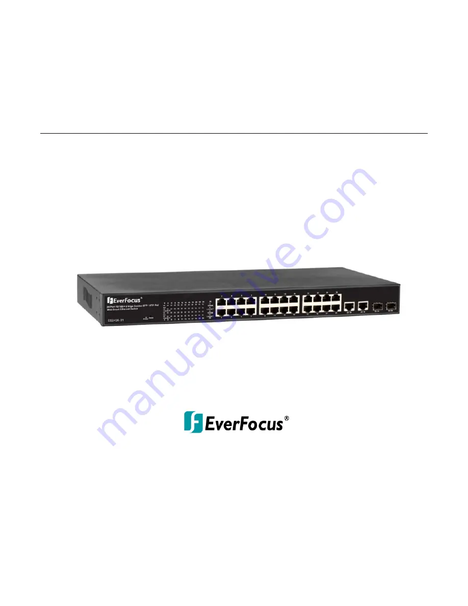
ES2426-31
24-port 10/100M PoE + 2 Gigabit Copper/SFP Combo Rackmount Web Smart PoE Switch
User’s Manual
Copyright © EverFocus Electronics Corp,
Release Date: September, 2013
Notice: This content is subject to be changed without notice.
Page 1: ... port 10 100M PoE 2 Gigabit Copper SFP Combo Rackmount Web Smart PoE Switch User s Manual Copyright EverFocus Electronics Corp Release Date September 2013 Notice This content is subject to be changed without notice ...
Page 2: ...erfocus Electronics Corporation Release Date September 2013 QuickTime is a registered trademark of the Apple Computer Inc Windows is a registered trademark of the Microsoft Corporation Linksys is a registered trademark of the Linksys Corporation D Link is a registered trademark of the D Link Corporation DynDNS is a registered trademark of the DynDNS org Corporation Other product and company names ...
Page 3: ...nce will not occur in a particular installation If this equipment does cause harmful interference to radio or television reception which can be determined by turning the equipment off and on the user is encouraged to try to correct the interference by one or more of the following measures Reorient or relocate the receiving antenna Increase the separation between the equipment and receiver Connect ...
Page 4: ...el 5 2 5 Hardware Installation 5 3 User Log In 6 4 Administrator 8 4 1 Authentication Configuration 8 4 2 System IP Configuration 8 4 3 System Status 9 4 4 Load Default Setting 10 4 5 Firmware Update 11 4 6 Reboot Device 11 5 Port Management 12 5 1 Port Configuration 12 5 2 Port Mirroring 13 5 3 Bandwidth Control 14 5 4 Broadcast Storm Control 14 5 5 PoE 15 6 VLAN Setting 16 6 1 VLAN Mode 16 6 2 V...
Page 5: ...ased 22 9 Security 23 9 1 MAC Address Binding 23 9 2 CP UDP Filter 24 10 Spanning Tree 25 10 1STP Bridge Settings 25 10 2STP Port Settings 26 10 3Loopback Detection Settings 27 11 Trunking 28 12 Backup Recovery 29 13 Miscellaneous 30 14 Logout 31 15 Specification 32 ...
Page 6: ... better traffic management reduces latency improve security and save bandwidth This is also a cost saving feature as it reduces the need to add additional hardware to the network These 24 10 100Mbps RJ 45 support the IEEE 802 3at PoE protocol Each port and transmit a maximum power 30 watts User can also enable or disable power supply on PoE ports from UI 1 2Web Management Features Port Management ...
Page 7: ...ad Link Aggregation IEEE 802 1d Spanning tree protocol IEEE 802 1w Rapid Spanning tree protocol IEEE 802 1x Port based Network Access Control IEEE 802 1Q VLAN IEEE 802 1p Class of Service Number of Port 24 port 10 100BaseTX with PoE 2 port Combo Gigabit uplink RJ 45 SFP 1 4Mechanical LED Indicator Per Port Link Act PoE Port Act Status Per Unit Power Power Consumption 400Watts Max Power Input 100 2...
Page 8: ...Mb Transmission Method Store and Forward 1 6Package Contents Before you start to install this switch please verify your package that contains the following items 1 One Fast Ethernet PoE Switch 2 One Power Cord 3 One User Manual 4 One pair Rack mount kit 8 Screws ...
Page 9: ...ch consists of 24 10 100Base TX RJ 45 ports and 2 combo gigabit uplink RJ 45 SFP ports The LED Indicators are also located on the front panel 2 3LED Indicators The LED Indicators present real time information of systematic operation status The following table provides description of LED status and their meaning LED Status Description No Of LED Power On Power on Power 1000M On Link 1000Mbps 2 25 26...
Page 10: ...witch right side shown as below 2 5Hardware Installation Set the switch on a large flat space with a power socket close by The flat space should be clean smooth level and sturdy Make sure there is enough clearance around the switch to allow attachment of cables power cord and allow air circulation The last use twisted pair cable to connect this switch to your PC then user could start to operate th...
Page 11: ...e first open the web browser and go to 192 168 2 1 site then the user will see the login screen Key in the password to pass the authentication then clicks the OK The log in process is completed and comes out the sign Password successfully entered Log in ID admin Password admin Figure 1 1 Note It will show error message if you key in wrong user name or password Figure 1 2 Chapter 3 ...
Page 12: ...ES2426 31 7 Main Page Figure 1 3 ...
Page 13: ...is page shows authentication configuration information User can set new Username and Password in this page Figure 2 1 4 2 System IP Configuration This page shows system configuration including the current IP address and sub net mask and gateway Figure 2 2 Chapter 4 ...
Page 14: ...in screen automatically 4 3System Status This page displays the information about the switch of MAC address how many ports it has system version and Besides users can also fill in up to 15 characters in the Comment Contact and Location field for note Figure 2 3 MAC Address Displays the unique hardware address assigned by manufacturer default Number of Ports Displays number of ports in the switch S...
Page 15: ...e Base is described as following The purpose of this function is to provide a method for the network administrator to restore all configurations to the default value 1 To activate this function the user should follow the following procedures Press the Load default button for 3 seconds until you see the LED blinking 2 When LED starts blinking it means the CPU is executing the load default procedure...
Page 16: ...ep intact Even though the power is turned off or the cable link fails during the firmware update procedure the Boot loader will restore the code to firmware update page Figure 2 5 After pressing Update button the old web code will be erased Then you can select the image file and press update button to update the firmware you need Figure 2 6 4 6Reboot Device Click Confirm button to reboot the devic...
Page 17: ...ated automatically When you set it as Disable you have to assign those items manually Speed When the Auto Negotiation column is set as Disable users have to set the connection speed to the ports ticked Duplex When the Auto Negotiation column is set as Disable users have to set the connection mode in Half Full to the ports ticked Pause Flow Control for connection at speed of 10 100Mbps in Full dupl...
Page 18: ...rts can be monitored by any of the ports means traffic goes in or out monitored source ports will be duplicated into mirroring destination port Figure 3 2 Destination mirroring port for monitoring Rx only Tx only or both RX and TX traffic which come from the source port Users can connect the mirroring port to LAN analyzer or Netxray Monitored Packets Pull down the selection menu to choose what kin...
Page 19: ...the selected bandwidth resolution to get the actual bandwidth Figure 3 3 5 4Broadcast Storm Control The switch implements a broadcast storm control mechanism Tick the check boxes to have them beginning to drop incoming broadcast packets if the received broadcast packet counts reach the threshold defined Each port s broadcast storm protection function can be enabled individually by ticking the chec...
Page 20: ...he switch treats it as the normal traffic Threshold Type in the threshold in the range between 1 and 63 to limit the maximum byte counts which a port can send or receive in a period of time Enable Port Having ticked the boxes the port will stop transmitting or receiving data when their sending byte counts or receiving byte counts reach the defined threshold Click Update to have the configuration t...
Page 21: ... traffic within VLAN groups to other switches For the handover to other switches use Tag Based VLAN In VLAN Mode you can switch from Tag to Port Based VLAN Port Based VLAN is the default mode After having switched to Tag Based VLAN Mode the screen changes On this screen you can now define and configure your Up and Downlink ports These are important since here the handover between the switches of y...
Page 22: ... and Port Based VLAN Mode The screen here looks different whether you run Tag Based or Port Based Mode VLAN Member in Port Based Mode Figure 4 3 In Port Based Mode you see a matrix of your 8 Ports Simply select the port on top screen you want to configure click on Read and then select or deselect the ports that are on the same VLAN group In this configuration mode you do not need to worry about de...
Page 23: ...gives you enough free room and less compatibility issues So enter 100 in the field right of VID Setting then select or deselect which ports are member of that group Your up and downlink ports need to member of every existing group Then click on add The new group with its setting will be displayed at the bottom of the screen With the PVID Setting you define to which VLAN group incoming traffic belo...
Page 24: ...VLAN Member Setting When VLAN member Setting is updated multi to 1 setting will be void and vice versa The disable port means the port which will be excluded in this setting All ports excluded in this setting are treated as the same VLAN group In a normal Tag Based VLAN network you will not need this configuration option Figure 4 5 ...
Page 25: ...he received packet count excluding the incorrect packet and the transmitted packet count Collision Count Transmit packet This category shows the packets outgoing from the switch and the count of collision Drop packet Receive packet This category shows the number of received valid packet and the number of dropped packet CRC packet Receive packet This category shows the received correct packet and r...
Page 26: ...entify such classes but they do not guarantee delivery as do quality of service QoS functions which are implemented in the network devices 8 1Priority Mode There are three priority modes available to specify the priority of packets being serviced Those include First In First Out All High Before Low and Weight Round Robin Figure 6 1 First In First Out Packets are placed into the queue and serviced ...
Page 27: ...ES2426 31 22 8 2Port 802 1p IP DS based Figure 6 2 ...
Page 28: ... addresses to the port Read Pull down the selection bar to choose a port number and click the read button to show the MAC addresses bound with the port or modify the MAC addresses Select Port Pull down the selection menu bar to choose a port number to be set Binding Enable or disable the binding function Click Update to have the configuration take effect Chapter 9 ...
Page 29: ...ES2426 31 24 9 2 CP UDP Filter Figure 7 2 ...
Page 30: ...ts of 4096 Therefore there are 16 distinct values Hello Time Interval in seconds at which the root device transmits a configuration message BPDU frame Number between 1 10 default is 2 Max Age The maximum time in seconds a device can wait without receiving a configuration message before attempting to reconfigure That also means the maximum life time for a BPDU frame Number between 6 40 default is 2...
Page 31: ...est path between devices Therefore lower values should be assigned to ports attached to faster media and higher values assigned to ports with slower media Set the RSTP path cost on the port Number between 0 200000000 0 means auto generated path cost State Show the current port state includes designated port root port or blocked port Status Show the current port status includes forwarding disable e...
Page 32: ...ES2426 31 27 10 3 Loopback Detection Settings Figure 8 3 ...
Page 33: ...in the trunk group causes the network traffic to be directed to the remaining ports Load balancing is maintained whenever a link in a trunk is lost or returned to service This switch may use Port ID Source MAC Address Destination MAC Address or a combination of Source MAC Address and Destination MAC Address to be the selection for Trunk Hash Algorithm Traffic pattern on the network should be consi...
Page 34: ...configuration The user can save configuration file to a specified file If the user wants to recover the original configuration which is saved at the specified path just enter the password and then press the upload button Finally the original configuration of the switch will be recovered Figure 10 1 Chapter 12 ...
Page 35: ...ecome a useless packet To prevent these packets from wasting the bandwidth this switch provide an option for the administrator to enable the queue aging function VLAN Striding By selecting this function the switch will forward uni cast packets to the destination port no matter whether destination port is in the same VLAN IGMP Snooping When this function is enabled the switch will execute IGMP snoo...
Page 36: ...ault setting Please take the following steps to reset the Web Smart Switch back to the original default Step 1 Turn on the Web Smart Switch Step 2 Press and hold the reset button continuously for 5 seconds and release the reset button Step 3 The switch will reboot for 20 seconds and the configuration of switch will back to the default setting Key in the user ID and the password to pass the authent...
Page 37: ... PoE Features Number of Ports 26 10 100BaseTX with RJ 45 Connectors 24 port with PoE Gigabit Uplink 2x 10 100 1000BaseT RJ 45 Gigabit SFP Combo Port MAC Address 4K Buffer Memory 2 75Mb Transmission Method Store and Forward Smart Features Port Based VLAN 26 Tagged Based VLAN 32 VID 1 4094 STP RSTP IGMP Snooping V1 V2 Link Aggregation 3 groups Quality of Service QoS High Low queues 802 1p Security P...
Page 38: ...ps Transmission Media 10 100BaseTX Cat 5 UTP STP 1000BaseT Cat 5 Cat 5E UTP STP LED Indicators Per Port Link Act PoE Act Status Per Unit Power Power Input 100 240 V AC 50 60Hz Power Output 53V DC Per Port Output Power Consumption 400 Watt Max Dimensions 44 440 332 mm H x W x D Operating Temperature 0 to 40 Storage Temperature 20 to 90 Humidity 10 to 90 RH non condensing Certifications FCC Class A ...
Page 39: ...3 5625 8189 www everfocus co jp info everfocus co jp EverFocus Europe UK Unit 12 Spitfire Business Park Hawker Road Croydon Surrey CR0 4WD UK TEL 44 20 8649 9757 44 845 430 9999 FAX 44 20 8649 9907 www everfocusuk co uk salesuk everfocus com EverFocus India Suite 803 Housefin Bhavan C 21 Bandra Kurla Complex Bandra East Mumbai 400051 India TEL 91 22 6128 8700 FAX 91 22 6128 8705 www everfocus in s...