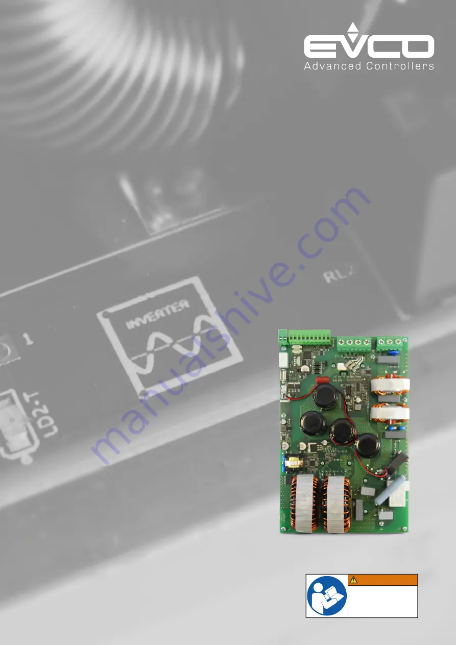
Syncro series inverter
Inverter for high power synchronous motors
WARNING
Make sure you read and fully
understand the user manual
before using this device.
Non-observance of these
instructions will result in death
or serious injury.
114EIXKE4.00 - 02/2022
Hardware Manual


