background image


25  

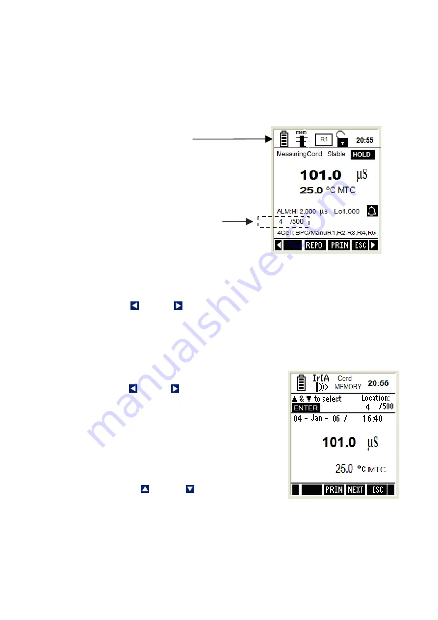
5.2.1  Logging data automatically in the meter’s memory 

1.  Make sure that the Print mode is set to ‘data logging mode’ in the System 

Setup. You can also specify the time interval for each transfer.  

2. 

From measurement mode, press 

PRIN (F3)

 to start saving data 

automatically in meter’s memory. The memory location of the transferred 
reading is shown in the bottom-left of the screen.


5.2.2  Storing a current measurement 

(In IrDA and LED print mode: Applicable to all 

modes)


1.  Make sure you are in the measurement mode. 
2. Press left   or right   arrow key to navigate to other available functions 

until you see 

STOR

 function in the LCD. 

3. Press 

STOR (F3)

 key to store the current reading. The bottom left of the 

screen will show the memory location where this reading is being saved. 

5.2.3  Viewing stored data 

1.  Make sure you are in measurement mode. 
2. Press left   or right   arrow key to navigate to 

other available functions until you see 

MEM


function in the LCD. 

3. Press 

MEM (F2)

 key to view the stored data. 

The last data entry stored is shown in the 
display with its memory location at the top-right 
corner of the screen [Immediately under the 
time]. (See following diagram) 

4. To navigate to a particular memory location, 

press the up   or down   arrow key to select it 
and then press the 

ENTER

 key. The meter will 

show the stored data in the memory location you selected. 

5. Press 

NEXT (F3)

 key to return to the measurement mode. 

6. Press 

ESC (F4)

 key to return to the main screen of the measurement mode. 

Memory Location 
where readings are 
being saved

NOTE:


This symbol will 

appear if data logging mode 
has been selected in “System 
set up’. It will automatically 
start saving data in meter’s 
memory, when 

PRIN (F3)

 key 

is pressed. 

Summary of Contents for CD 650

Page 1: ... Instruction Manual WP 600 Series Meters pH 600 610 620 COND 600 610 DO 600 PC 650 PD 650 CD 650 PCD 650 Part of Thermo Fisher Scientific 99 Washington Street Melrose MA 02176 Phone 781 665 1400 Toll Free 1 800 517 8431 Visit us at www TestEquipmentDepot com ...

Page 2: ......

Page 3: ...brate your instrument Pages 1 39 Step 2 Then go to the specific parameter guides eg pH Conductivity TDS etc which are relevant to the model you have purchased Pg 41 onwards CAUTION Do not skip the general guide as your meter will not be configured to read accurately if your set up and calibrations are not done accordingly Thank you for reading this page Please proceed ...

Page 4: ......

Page 5: ... Measurement Mode 21 4 1 1 Accessing functions 21 4 2 Taking Measurements 22 4 2 1 Prepare the meter for measurement 22 4 2 2 Taking a reading 22 4 2 3 Stable reading indicator 23 4 2 4 Holding a reading 23 4 3 Automatic Temperature Compensation ATC 23 4 3 1 Manual Temperature Compensation MTC 23 4 4 Alarm set point For pH conductivity DO 24 4 5 Calibration Due CAL DUE Indicator For pH conductivit...

Page 6: ...easurement screen 51 mV 52 1 mV Setup Mode 54 2 mV Calibration Mode 54 2 1 mV Calibration with a Standard ORP Calibration Solution 54 2 2 Calibration Report 55 2 2 1 To View Calibration Report 55 3 mV Measurement Mode 55 3 1 Indicators in mV measurement mode 55 ION 58 1 Ion Setup 60 2 Ion Calibration Mode 60 2 1 About Ion Calibration 60 2 2 Calibration Report 62 2 2 1 To View Calibration Report 62...

Page 7: ...ty Calibration Report 96 2 1 1 To View Calibration Report 96 3 Resistivity Measurement Mode 97 3 1 Indicators in Resistivity measurement mode 97 DISSOLVED OXYGEN 99 PART A Saturation Mode 101 1 O2 DO Saturation Setup 101 2 DO Calibration in Saturation Mode with ATC 103 2 1 About DO and DO mg L Calibration 103 2 2 To calibrate 100 saturation 103 2 3 To calibrate 0 saturation 105 2 3 1 DO Calibratio...

Page 8: ...113 3 1 Indicators in concentration measurement screen 113 3 2 Dissolved Oxygen Probe 114 3 2 1 Dissolved Oxygen Principle 114 3 2 2 Probe Care 115 3 2 3 Membrane Housing Replacement 115 3 2 4 Membrane O ring Replacement Optional Procedure 116 3 2 5 Electrolyte Solution 117 ...

Page 9: ...ution to 0 001 and Ion COND 600 Temperature with ATC Conductivity TDS COND 610 Temperature with ATC Conductivity TDS Salinity Resistivity DO 600 Temperature with ATC Dissolved Oxygen ppm PC 650 Temperature with ATC pH mV Ion Conductivity TDS Salinity Resistivity PD 650 Temperature with ATC pH mV Ion Dissolved Oxygen ppm CD 650 Temperature with ATC Conductivity TDS Salinity Resistivity Dissolved Ox...

Page 10: ...2 ...

Page 11: ... for calibration setup data Intuitive on screen messages appear to assist user 1 1 1 Display Overview 1 1 2 Key Functions Key Function Selects the function shown in the display just above the key For ON key press and hold for 3 seconds Navigates to next available functions Increment decrement values in Setup Calibration modes Navigates to sub groups in Setup selection screen In Setup mode confirms...

Page 12: ...he battery cover 2 Insert the batteries in the right direction 3 Replace the battery cover and screws Note the UP symbol marked on the cover 4 Press the ON F4 key Hold the key down until the display appears 5 Set the system date time before you start operating the meter for the first time 1 2 2 Changing batteries subsequently 1 Connect the adapter before changing the batteries 2 If DC adapter is n...

Page 13: ...he battery cover 2 Insert the safety belt through the two slots as indicated below 3 Screw the battery cover back on Note the UP symbol marked on the cover 4 Insert your palm between the belt and the body of the meter and adjust the hook loop fastener Note the correct side of the belt Battery Cover Hook Loop fastener ...

Page 14: ...shown 3 Be sure to remove the protective electrode storage bottle or rubber cap of the pH electrode before calibration or measurement NOTE If the electrode has been stored dry wet the electrode in clean water for 10 minutes before calibrating or taking readings to saturate the pH electrode surface and to minimize drift pH Probe BNC Conductivity Probe with built in temperature sensor 8 pin Connecto...

Page 15: ...The rubber boot protects the meter when used in the field For bench top applications lift up the stand at the back of the rubber boot PLEASE SET UP THE SYSTEM BEFORE YOU BEGIN USING THE METER USE THE FOLLOWING OVERVIEW FOR SETUP MODE ...

Page 16: ...or more information Temperature Temperature measurement calibration related settings 2 2 Accessing Setup mode 1 Switch the meter on The meter goes to measurement mode 2 Press left or right arrow key on the keypad to navigate to other available functions until you see SETP function in the LCD 3 Press SETP F1 and Setup Key Function screen appears This page describes the key functions for configuring...

Page 17: ...Selection Screen Function keys available in setup selection screen F1 Not functional F2 Not functional F3 Not functional Goes to required setup sub groups ENTER Selects the current sub group ESC F4 Goes to measurement mode from where you entered setup Not functional 2 3 Setup Selection System Settings System Settings Page 1 General Settings Figure 2 System Settings Page 1 General Settings ...

Page 18: ...e reading is Stable for 5 seconds If this is enabled Response time appears in the measurement screen indicating the average response time of the probe DISABLE The reading is not held This parameter has no effect if STABLE parameter is disabled The response time may not work if the system time has not been set as described previously DISABLE Tem Display from Allows you to select temperature from pH...

Page 19: ...e for the current time 00 Second Sets the second for the current time 00 System Settings Page 3 Auto Off Backlight Figure 4 System Settings Page 3 Auto Off Backlight This page allows you to set auto off and back light related parameters Parameter Description Factory Default Auto OFF ENABLE Turns the meter off automatically if no key is pressed for the time period specified in ON TIME below However...

Page 20: ...fore automatically turning off the back light after the last key is pressed This parameter is not editable when BACK LIGHT Key press is disabled This parameter has no effect if BACK LIGHT Always parameter is set to ON 1 min System Settings Page 4 Wireless Serial Data Communication Figure 5 System Settings Page 4 Wireless Serial Data Communication This allows you to set wireless serial data communi...

Page 21: ... is set to TIMED and this is not editable when CURRENT DATA SET is set to SINGLE 9 Sec Fixed Setting Indicates serial communication settings in the format of Baud rate Data bits Parity bits Stop bits This parameter is not editable 2400 8 N 1 System Settings Page 5 Password Protection This allows you to enable password protection for the setup mode calibration mode Figure 6 System Settings Page 5 P...

Page 22: ...assword NO System Settings Page 6 Data Memory Factory Settings Figure 7 System Settings Page 6 Data Memory Display Contrast Factory Settings Clear logged Data Memory NO Display Contrast 12 Factory Reset NO Important 1 Please memorize the password that you have entered after enabling the password protection Without it you can t disable the password protection or reset the meter to factory defaults ...

Page 23: ...leting your calibration data Resetting setup parameters to factory defaults except date time Deleting your stored data in the memory NO Select this if you do not wish to reset the meter When YES is selected and confirmed by pressing ENETR key the meter is reset to factory defaults and then the meter goes to measurement mode NO 2 4 Accessing Setup mode when password protection enabled 1 Switch the ...

Page 24: ...n arrow key to change the value of a selected parameter 3 Once you have changed a value Press ENTER key to save the change or Press NEXT F3 key to go to the next parameter without saving the changed parameter 4 Press NEXT P F2 or PRE P F1 to navigate to next or previous page 5 Press ESC F4 to exit from setup mode Refer to Page 9 for current function keys settings Note You can enter 00000 read only...

Page 25: ...an perform a single or multi point calibration You will need to set your meter to single or multi point calibration in the Setup mode for conductivity resistivity TDS or salinity Refer to the setup section for the particular mode you will be measuring Instead of calibrating for TDS directly using TDS calibration standard solutions you can have TDS calibration by using the conductivity calibration ...

Page 26: ...ppm calibrate the meter at least once a week to ensure accuracy If you are measuring in the mid ranges and you wash the electrode in de ionized water and store it dry calibrate the meter once a month If you take measurements at extreme temperatures calibrate at least once a week Ensure that you use new conductivity standard solutions or sachets during calibration Do not reuse standard solutions as...

Page 27: ... the measurement mode for which you wish to perform calibration 2 Press CAL F2 to go to calibration mode Login Password screen appears Figure 9 The meter expects the 5 digit password specified in system setup Figure 9 Login Password 1 Press up down arrow keys to enter the first digit of the password and then press NEXT F3 key to move to the next digit 2 The next digit is selected Press up down arr...

Page 28: ...20 ...

Page 29: ...as used before it was turned off the last time Press MODE F3 key to select your required measurement mode 4 1 1 Accessing functions There are many functions available in the measurement mode Use the 4 Function keys F1 F2 F3 F4 to access them The first group of functions appear when you enter the measurement mode Press the left or right arrow key to navigate to the 2nd and 3rd function groups Funct...

Page 30: ...pplication through IrDA If data logging mode has been selected in System Setup then it sends data automatically to meter s memory ESC F4 Shows 1st Group of functions Switches between functions groups available in measurement mode ENTER Not functional Not functional Note If you press a function key that is not relevant to measurement mode for example ENTER the meter shows Invalid key message in the...

Page 31: ... consecutive seconds This feature needs to be enabled in the setup Press HOLD F1 key to release the reading 4 3 Automatic Temperature Compensation ATC Connect an appropriate probe to the meter and select ATC mode in the temperature setup for the pH conductivity DO reading to be automatically compensated for temperature variations If you select ATC without connecting a probe to the meter the LCD wi...

Page 32: ...the days elapse from your last calibration date 5 TRANSFERRING AND PRINTING DATA Please refer to this section after completing calibrations and taking measurements 5 1 CyberComm 600 Data Acquisition Software Your meter is shipped with a companion software application called CyberComm 600 Data Acquisition Software DAS For details on installation connection and usage of the software please read the ...

Page 33: ...reading is being saved 5 2 3 Viewing stored data 1 Make sure you are in measurement mode 2 Press left or right arrow key to navigate to other available functions until you see MEM function in the LCD 3 Press MEM F2 key to view the stored data The last data entry stored is shown in the display with its memory location at the top right corner of the screen Immediately under the time See following di...

Page 34: ...to select either all memory locations or the current memory location and then press ENTER key 6 If you have selected ALL LOCATIONS then you can specify the time interval in between each transfer Press up or down arrow key to select from 1 to 50 second intervals then press ENTER key 7 At the CyberComm screen on your computer press Find Device button 8 Once CyberComm finds the meter click the Connec...

Page 35: ...ou can use an RS 232C Adapter sold separately that connects directly to your PC using a specially designed 9 pin plug Then use the Cybercomm or HyperTerminal software to print your data You can also use the RS232C Adaptor to print your data directly to our dot matrix microprinter sold separately using a custom built 25 pin plug Please contact your dealer to find out more ...

Page 36: ...ccessories page at the back of this manual and transfer data from your meter using the USB port Please note This accessory is specially engineered to match your meter s software to the application in your laptop or PC If you purchase this item from a different source it will NOT be compatible for transferring the data ...

Page 37: ...ffer Options 15 Calibration due alarm User configurable up to 30 days Set point alarm User configurable Auto buffer recognition Yes pH buffer Groups Calibration Points USA 1 68 4 01 7 00 10 01 12 45 NIST 1 68 4 01 6 86 9 18 12 45 DIN 1 09 3 06 4 65 6 79 9 23 12 74 PWB 4 10 6 97 USA 1 5 pH for 7 00pH 1 pH for all other buffers NIST 1 35 pH for 6 86pH 1 pH for all other buffers DIN 0 8 pH for 1 09 3...

Page 38: ...m to 99 99ppm 100 0ppm to 300 0ppm 300 0ppm to 999 9ppm 1 000ppt to 4 000ppt 4 000ppt to 9 999ppt 10 00ppt to 40 00ppt 40 00ppt to 99 99ppt 100 0ppt to 500 0ppt 0 01ppm 0 01ppm 0 01ppm 0 1ppm 0 1ppm 0 001ppt 0 001ppt 0 01ppt 0 01ppt 0 1ppt Display resolution is 0 001 but actual resolution shows 0 01 1 of FS 1 of FS 1 of FS 1 of FS 1 of FS 1 of FS 1 of FS 1 of FS 1 of FS 1 of FS Salinity Range Meas...

Page 39: ...0 to 200mS 0 to 500 mS Salinity 80 ppt Resistivity 0 to 20 00MΩ TDS 200 ppt depending on TDS factor 500 ppt depending on TDS factor Conductivity Cell constant 0 010 to 10 000 Conductivity Cell 2 4 Cell TDS Conversion Factor 0 400 to 1 000 Temperature Comp Linear Linear Pure Cal Auto Manual Yes Cal Single Multi Yes Cal Due Alarm Yes max 30 days Set Point Alarm Yes Input Conductivity 8 Pin Round Dis...

Page 40: ...ata logging Yes GLP Good Lab Practice Yes Ingress protection IP 67 Dimensions 95mm W x 185mm L x 58 5mm H Without Rubber Boot 101mm W x 191mm L x 61mm H With Rubber Boot Weight 380g Without Rubber Boot Power Input pH 600 610 620 All other models Battery 4 x Alkaline AA size 1 5 V Battery Life 500 Hrs without backlight serial data transfer 200 Hrs without backlight serial data transfer Power adapte...

Page 41: ... 5 01X241603 Assembled Membrane Cap Housing 15X241402 Membrane removal tool 15X241502 Electrode Guard Removal Tool 15X241504 DO Refilling electrolyte 60 mL 01X211226 Rubber Boot for 600 series meters ECRUBBERBT600 100 240VAC Power Adapter 01X030132 USB irDA Converter 1 1 Standard 01X447601 Oakton Instruments Product Description Oakton Instruments Order Code 8 pin connector Temperature probe 3m Cab...

Page 42: ...ower Adapter 35418 83 Carrying Case with 4 sets of empty 60 ml bottle 35632 99 8 Warranty Return Policy 8 1 Warranty Eutech Instruments supplies this meter with a 3 year warranty and 6 month warranty for electrode against manufacturing defects from the date of purchase If repair or adjustment is necessary and has not been the result of abuse or misuse within the designated period please return fre...

Page 43: ...aging is the user s distributor s responsibility Please follow the guidelines below before shipment 8 3 Guidelines for Returning Unit for Repair Use the original packaging material if possible when shipping the unit for repair Otherwise wrap it with bubble pack and use a corrugated box for additional protection Include a brief description of any faults suspected for the convenience of Customer Ser...

Page 44: ...MPERATURE PARAMETER GUIDE i Temperature Setup Mode ii Temperature Calibration ATC and MTC Mode iii Temperature Measurement Mode FOR ALL MODELS pH 600 610 620 COND 600 610 DO 600 PC 650 PD 650 CD 650 PCD 650 ...

Page 45: ...37 ...

Page 46: ...ried out prior to pH conductivity and DO calibration since temperature readings affect the accuracy of pH conductivity and DO measurements You need to perform temperature calibration only if the temperature value displayed on the meter is different from that of a calibrated thermometer or if cell constant setting is changed A temperature offset calibration of 5 C 9 F from the default reading is al...

Page 47: ... In pH mode pressing this key will take you to the Report page 4 Press TEMP F1 to go to temperature calibration The temperature calibration screen appears Figure 14 Temperature Calibration Screen 1 The screen shows two readings The upper display shows the temperature reading of the solution with respect to previous calibration if any lower displays shows the temperature reading of the solution wit...

Page 48: ...h respect to previous calibration if any lower displays shows the temperature reading of the solution without any calibration default reading Use keys to adjust the upper display to the temperature reading of the thermometer 6 Press ENTER key to confirm temperature value Function Keys available in temperature calibration screen NEXT F3 Goes to measurement mode from where you entered calibration ES...

Page 49: ...41 ...

Page 50: ...42 pH PARAMETER GUIDE 1 pH Setup Mode 2 pH Calibration Mode 3 pH Measurement Mode FOR MODELS pH 600 610 620 PC 650 PD 650 PCD 650 ...

Page 51: ...43 ...

Page 52: ...ts Select the number of calibration points you intend to calibrate the meter using the selected buffer group Available points depends on the selected buffer group 3 Alarm Set Point ENABLE The measurement screen shows HI or LO alarm indicators when the meter reading is above HI alarm value or below LO alarm value specified in HI pH LO pH parameters below DISABLE HI and LO alarms are not shown in th...

Page 53: ... replaced on a point by point basis For example if you previously calibrated your meter at pH 4 01 7 00 and 10 01 and you have now re calibrated at pH 7 00 the meter retains the old calibration data at pH 4 01 and pH 10 01 The meter shows previously calibrated points in the display when the meter is in pH measurement mode To completely re calibrate the meter or when you use a replacement probe it ...

Page 54: ... group 2 2 1 pH Calibration points This option allows you to calibrate up to 6 points depending on the standard buffer selected Or you can choose to have custom buffers with 2 to 5 points When completely re calibrating the meter the first point of calibration should be one of the following depending on your choice of standard buffer group The meter automatically recognizes and calibrates to the st...

Page 55: ...Rinse the probe with clean water 9 Place it in the next buffer and follow steps 5 and 7 to calibrate other points Function Keys available in pH Calibration mode TEMP F1 Goes to temperature calibration CLR C F2 Clears previous calibration if any after ENTER key is pressed in confirmation screen NEXT F3 Shows calibration report ESC F4 Exits from calibration and goes back to pH measurement mode ENTER...

Page 56: ...he solution without any calibration Use keys to adjust the upper display to the pH value of your custom buffer 4 Press ENTER key to confirm the calibration 5 Rinse the probe with clean water Place it in the next buffer and follow steps 2 3 and 4 to calibrate other points Function Keys available in pH Calibration mode TEMP F1 Goes to temperature calibration CLR C F2 Clears previous calibration if a...

Page 57: ...shown in the display 3 Press PAGE F1 to view the second page of the report 4 Press PRIN F2 to transfer the calibration report to computer through IrDA Figure 19 pH Calibration Report Example In the given pH calibration report 4 point calibration has been done for USA buffer group pH 1 68 pH 4 01 pH 7 00 pH 12 45 The slope is 93 for the range enveloped from pH 1 68 to pH 4 01 The slope is 88 for th...

Page 58: ...be and graphically indicates it in the header section of the LCD screen Figure 20 Average Slope Indicator Number of bars in the indicator shows the slope value Number of Bars Average Slope of the pH Probe 4 Above 90 3 90 to 80 2 80 to 70 1 Below 70 3 pH Measurement Mode 3 1 Resolution of pH Reading By default the resolution is set to 0 00 You can change the resolution in the setup mode pH resoluti...

Page 59: ...easurement mode indicator 2 Appears when the reading is stable 3 Appears when the reading is on hold 4 pH reading 5 Units of measurement 6 Temperature reading units 7 Temperature compensation mode 8 pH HI LO Alarm limits 9 pH Alarm indicator 10 Calibration Due indicator 11 Response time of the pH probe 12 Calibrated Points 1 4 6 8 12 3 2 5 9 11 10 7 ...

Page 60: ...52 mV PARAMETER GUIDE 1 mV Setup Mode 2 mV Calibration Mode 3 mV Measurement Mode FOR MODELS pH 600 610 620 PC 650 PD 650 PCD 650 ...

Page 61: ...53 ...

Page 62: ... Figure 21 mV Calibration Screen Calibration Report 4 The screen shows two readings The upper display shows the mV reading of the solution with respect to previous calibration if any lower displays shows the absolute mV reading of the solution without any calibration default reading Use keys to adjust the upper display to the mV value of the solution 5 Press ENTER key to confirm the entered value ...

Page 63: ...le functions until you see REPO function in the LCD 2 Press REPO F2 key The calibration report is shown in the display 3 Press PRIN F2 to transfer the calibration report to the computer 3 mV Measurement Mode In mV measurement mode the meter displays mV and temperature reading Depending on application you can connect a suitable ORP probe to the meter or use the pH probe 3 1 Indicators in mV measure...

Page 64: ...of the solution in measurement mode END OF mV SECTION Item Description 1 Measurement mode indicator 2 Appears when the reading is stable 3 Appears when the reading is on hold 4 mV reading 5 Units of measurement 6 Temperature reading units 7 Temperature compensation mode ...

Page 65: ...57 ...

Page 66: ...58 ION PARAMETER GUIDE 1 Ion Setup Mode 2 Ion Calibration Mode 3 Ion Measurement Mode FOR MODELS pH 620 PC 650 PD 650 PCD 650 ...

Page 67: ...59 ...

Page 68: ...ble 8 points are 0 001 0 01 0 1 1 10 100 1000 10000 The meter guides your through the calibration process with on screen instructions and hints If the second point and subsequent points are not within the allowable calibration window 15mV decade to 90mV decade the meter will not accept the calibration When you try to re calibrate the meter with ISE the meter gives you 2 options Clear the previous ...

Page 69: ...shows the lowest calibration point 0 001 ppm The lower display shows the absolute mV reading of the solution without any calibration default reading Use keys to select the required calibration point in the upper display 6 Allow time for the reading to stabilize Press ENTER key to confirm the selected point The meter flashes the upper display to acknowledge the first point calibration Note If the m...

Page 70: ...56 0mV 156mV The slope is 56 mV decade for the range enveloped from 0 01 to 0 1 ppm Similarly the slope is 50 for the range enveloped from 0 1 to 10ppm where 0 1 calibration point has been skipped 2 2 1 To View Calibration Report 1 From ION measurement mode press left or right arrow key to navigate to other available functions until you see REPO function in the LCD 2 Press REPO F2 key The calibrat...

Page 71: ... measurement By default the measuring unit is ppm You can select either molar or mg L in the setup mode 3 2 Indicators in Ion measurement mode Figure 26 Ion measurement screen END OF ION SECTION Item Description 1 Measurement mode indicator 2 Appears when the reading is stable 3 Appears when the reading is on hold 4 Ion reading 5 Units of measurement 6 mV reading 1 4 5 6 3 2 Note If ion calibratio...

Page 72: ...64 CONDUCTIVITY PARAMETER GUIDE 1 COND Setup Mode 2 COND Calibration Mode 3 COND Measurement Mode FOR MODELS COND 600 610 PC 650 CD 650 PCD 650 ...

Page 73: ...65 ...

Page 74: ...temperature that the meter will use along with the temperature coefficient to calculate a temperature corrected conductivity measurement 25 Cell Constant Select the appropriate cell constant of the conductivity cell Available cell constants 0 1 to 10 1 000 Calibration due Specify number of days for the Conductivity calibration alarm The meter shows CAL DUE indicator after calibration date Availabl...

Page 75: ...arameters below DISABLE HI and LO alarms are not shown in the LCD DISABLE Hi ms Specify Hi alarm value here The Hi alarm occurs when the conductivity reading goes above this value Available range Hi µS specified below to 2 000 µS This parameter is not editable when ALARM SET POINT is disabled 2 000 µS Lo µs Specify Lo alarm value here The Lo alarm occurs when the conductivity reading goes below th...

Page 76: ...calibrate one point in each of the measuring ranges up to 5 points The selected calibration point will be displayed in the bottom of screen For example If single point calibration is selected it will display SPC at the bottom of the screen as shown in this diagram Figure 29 Calibration Standard Point Indicator But if a multi point calibration option calibration for different ranges are indicated i...

Page 77: ...o create a homogeneous sample Allow time for the reading to stabilize 3 Press CAL F2 to start calibration 4 The meter shows the Calibration Rinse Electrode screen for a few seconds to prompt user to rinse electrode with de ionized water before calibration Figure 30 Calibration Screens 5 The meter then shows cell constant adjustment screen The upper display shows the cell constant of the conductivi...

Page 78: ...calibration and goes back to conductivity measurement mode ENTER Confirms the calibration Increases decreases conductivity cell reading Not functional 2 8 Automatic Calibration For Conductivity Calibration In the Automatic Calibration mode the meter is capable of accepting either single point or up to 4 points for multi point calibration with a maximum of 1 point per specific measurement range Sel...

Page 79: ...h de ionized water Place it in the next solution and follow the steps 2 3 and 4 to calibrate other points Function Keys available in Conductivity Calibration mode TEMP F1 Goes to temperature calibration CLR C F2 Clears previous calibration if any after ENTER key is pressed for the confirmation screen NEXT F3 Shows calibration report ESC F4 Exits from calibration and goes back to conductivity measu...

Page 80: ...libration report screen PRIN F2 Transfers calibration report to Computer through IrDA NEXT F3 Goes to conductivity measurement mode ESC F4 Goes to conductivity measurement mode ENTER Not functional Not functional 3 Conductivity Measurement Mode In conductivity measurement mode the meter displays conductivity and temperature readings The LCD shows related information for the conductivity measuremen...

Page 81: ...emperature reading units 7 Temperature compensation mode 8 Conductivity HI LO Alarm limits 9 Conductivity Alarm indicator 10 Calibration Due indicator 11 Response time of the CON probe 12 Conductivity ranges that have been calibrated 13 Number of calibration points and method of calibration Note Lower display shows 2Cell or 4Cell when a 2 cell or 4 Cell conductivity probe is connected 1 4 6 8 10 1...

Page 82: ...74 END OF CONDUCTIVITY SECTION ...

Page 83: ...75 TDS PARAMETER GUIDE 1 TDS Setup Mode 2 TDS Calibration Mode 3 TDS Measurement Mode FOR MODELS COND 600 610 PC 650 CD 650 PCD 650 ...

Page 84: ...76 ...

Page 85: ...ter will use along with the temperature coefficient to calculate a temperature corrected conductivity measurement 25 Cell Constant Select the appropriate cell constant of the conductivity cell Available cell constants 0 1 to 10 1 000 Calibration due Specify number of days for the Conductivity calibration alarm The meter shows CAL DUE indicator after calibration date Available range 0 to 30 if enab...

Page 86: ...is above HI alarm value or below LO alarm value specified in HI LO ppm parameters below DISABLE HI and LO alarms are not shown in the LCD DISABLE Hi ppm Specify Hi alarm value here The Hi alarm occurs when the TDS reading goes above this value This parameter is not editable when ALARM SET POINT is disabled 2 00 ppm Lo ppt Specify Lo alarm value here The Lo alarm occurs when the TDS reading goes be...

Page 87: ...hows the cell constant adjustment screen for TDS Figure 37 TDS Cell Constant Adjustment TDS Calibration Screen 4 The upper display of the TDS cell constant screen shows the cell constant of the cell lower display shows the measured value of the solution with adjusted cell constant Press keys to adjust the cell constant for your custom solution in upper display 5 Press ENTER key to confirm the ente...

Page 88: ...ion It includes date time of the last calibration and the cal factor 2 1 1 To View Calibration Report 1 From TDS measurement mode press left or right arrow key to navigate to other available functions until you see REPO function in the LCD 2 Press REPO F2 key to go to calibration report screen 3 Press PRIN F2 to transfer the calibration report to the computer Figure 38 TDS Report Screen Note The f...

Page 89: ...libration in the TDS mode 3 TDS Measurement Mode In TDS measurement mode the meter displays TDS and temperature reading 3 1 Indicators in TDS measurement mode Item Description 1 Measurement mode indicator 2 Appears when the reading is stable 3 Appears when the reading is on hold 4 TDS reading 5 Units of measurement 6 Temperature reading units 7 Temperature compensation mode 8 TDS HI LO Alarm limit...

Page 90: ... the TDS value is in ppm the conductivity value must be in µS if the TDS value is in ppt the conductivity value must be in mS Check your factor by multiplying the conductivity reading by the factor in the above formula The result should be in TDS value 4 2 Calculating Temperature Coefficients To determine the temperature coefficient of your sample solution use this formula Where tc Temperature coe...

Page 91: ...83 SALINITY PARAMETER GUIDE 1 Salinity Setup Mode 2 Salinity Calibration Mode 3 Salinity Measurement Mode FOR MODELS COND 610 PC 650 CD 650 PCD 650 ...

Page 92: ...84 ...

Page 93: ...ent Specify temperature coefficient to measure temperature corrected conductivity 2 100 Normalization Temp Select a default temperature that the meter will use along with the temperature coefficient to calculate a temperature corrected conductivity measurement 25 Cell Constant Select the appropriate cell constant of the conductivity cell Available cell constants 0 1 to 10 1 000 Calibration due Spe...

Page 94: ...e The Hi alarm occurs when the salinity reading goes above this value 2 00 ppm Lo ppt Specify Lo alarm value here The Lo alarm occurs when the salinity reading goes below this value This parameter is not editable when ALARM SET POINT is disabled 1 00 ppm Press Up or Down arrow key to set high or low alarm point 2 Salinity Calibration Mode Use a standard solution of known value for calibration Use ...

Page 95: ... readings The upper display shows the salinity reading of the solution with respect to previous calibration if any lower display shows the salinity reading of the solution without any calibration Use keys to adjust the upper display of the salinity value of your custom solution 7 Press ENTER key to confirm the entered value 8 Rinse the probe with de ionized water Place it in the next solution and ...

Page 96: ...l factor 2 1 1 To View salinity Report 1 From salinity measurement mode press left or right arrow key to navigate to other available functions until you see REPO function in the LCD 2 Press REPO F2 key The calibration report is shown in the display 3 Press PRIN F2 to transfer the calibration report to the computer Figure 42 Salinity Report Screen ...

Page 97: ...Salinity Measurement Screen END OF SALINITY SECTION Item Description 1 Measurement mode indicator 2 Appears when the reading is stable 3 Appears when the reading is on hold 4 Salinity reading 5 Units of measurement 6 Temperature reading units 7 Temperature compensation mode 8 Salinity HI LO Alarm limits 9 Salinity Alarm indicator 10 Response time 11 Calibration Due indicator 12 Number of calibrati...

Page 98: ...90 ...

Page 99: ...91 RESISTIVITY PARAMETER GUIDE 1 Resistivity Setup Mode 2 Resistivity Calibration Mode 3 Resistivity Measurement Mode FOR MODELS COND 610 PC 650 CD 650 PCD 650 ...

Page 100: ...92 ...

Page 101: ...ormalization Temp Select a default temperature that the meter will use along with the temperature coefficient to calculate a temperature corrected conductivity measurement 25 Cell Constant Select the appropriate cell constant of the conductivity cell Available cell constants 0 1 to 10 1 000 Calibration due Specify number of days for the Conductivity calibration alarm The meter shows CAL DUE indica...

Page 102: ...ter reading is above HI alarm value or below LO alarm value specified in HI LO Ω parameters below DISABLE HI and LO alarms are not shown in the LCD DISABLE Hi Ω Specify Hi alarm value here The Hi alarm occurs when the resistivity reading goes above this value This parameter is not editable when ALARM SET POINT is disabled 2 00 Ω Lo Ω Specify Lo alarm value here The Lo alarm occurs when the resisti...

Page 103: ...f the resistivity cell constant screen shows the cell constant of your cell lower display shows the measured value of the solution with adjusted cell constant Press keys to adjust the cell constant for your custom solution in upper display 5 Press ENTER key to confirm the entered value and to go to resistivity calibration screen 6 The screen shows two readings The upper display shows the resistivi...

Page 104: ...of calibration and the cal factor 2 1 1 To View Calibration Report 1 From resistivity measurement mode press left or right arrow key to navigate to other available functions until you see REPO function in the LCD 2 Press REPO F2 key The calibration report is shown in the display 3 Press PRIN F2 to transfer the calibration report to the computer Refer page Error Bookmark not defined to print data F...

Page 105: ...SECTION Item Description 1 Measurement mode indicator 2 Appears when the reading is stable 3 Appears when the reading is on hold 4 Resistivity reading 5 Units of measurement 6 Temperature reading units 7 Temperature compensation mode 8 Resistivity HI LO Alarm limits 9 Resistivity Alarm indicator 10 Response time 11 Calibration Due indicator 12 Number of calibration points and method of calibration...

Page 106: ...98 ...

Page 107: ...ode 2 DO Calibration in Saturation Mode with ATC 3 Percentage Saturation Measurement Mode PART B Concentration Mode mg L ppm 1 O2 DO Saturation Setup Mode 2 DO Calibration in mg L or ppm Concentration Mode 3 Concentration mg L ppm Measurement Mode FOR MODELS DO 600 CD 650 PD 650 PCD 650 ...

Page 108: ...100 ...

Page 109: ...ation 0 0 Calibration due Specify number of days for the DO calibration alarm The meter shows CAL DUE indicator after calibration date Available range 0 to 30 5 days Select Pressure Unit Sets the unit for barometric pressure Available units mmHg and kPa mmHg Measured Pressure Barometric pressure as measured by the instrument Adjusted Pressure User adjusted value Pressure Compensation ENABLE The me...

Page 110: ... above HI alarm value or below LO alarm value specified in HI LO parameters below DISABLE HI and LO alarms are not shown in the LCD DISABLE Hi DO Specify Hi alarm value here The Hi alarm occurs when the DO reading goes above this value This parameter is not editable when ALARM SET POINT is disabled 200 0 Lo DO Specify Lo alarm value here The Lo alarm occurs when the DO reading goes below this valu...

Page 111: ... For one point calibration it is recommended that you perform a 100 Saturation calibration in saturated air If you opt for 2 point calibration you can calibrate for 100 Saturation in saturated air and 0 Saturation using a zero oxygen solution The meters are capable of measuring barometric pressure with its built in pressure sensor In the event the pressure reading is inaccurate you can calibrate t...

Page 112: ...urement Wait for the reading to stabilize 6 Press ENTER key to confirm the calibration The meter automatically calibrates to 100 air saturation and returns to the measurement mode Figure 52 Saturation Measurement Screen Note If you wish to completely re calibrate the meter you need to clear the previous calibration data Press CLR C F2 key to clear previous calibration The meter shows you the confi...

Page 113: ... Calibration Rinse Electrode screen for a few seconds to prompt user to rinse electrode with de ionized water before calibration 4 The meter then shows saturation calibration screen Wait for the reading to stabilize 5 The primary display will show the current value of measurement 6 Press ENTER key to confirm the calibration The meter automatically calibrates to 0 saturation and returns to the meas...

Page 114: ...right arrow key to navigate to other available functions until you see REPO function in the LCD 2 Press REPO F2 key The calibration report is shown in the display 3 Press PRIN F2 to transfer the calibration report to computer through IrDA Figure 54 DO Calibration Report in Saturation Mode Function Keys available in saturation report screen PRIN F2 Transfers calibration report to Computer through I...

Page 115: ...ould be done at 92 1 This is relative to the pressure at sea level If the pressure comp is set to DISABLE then there would be no compensation for the pressure The calibration would be done at 100 irrespective of the altitude 3 Percentage Saturation Measurement Mode In percentage saturation measurement mode the meter displays saturation and temperature reading The LCD shows related information for ...

Page 116: ...O setup screen The settings are displayed in 2 pages Press NEXT P F2 and PREV P F1 to navigate through these pages DO mg L Page 1 Item Description 1 Measurement mode indicator 2 Appears when the reading is stable 3 Appears when the reading is on hold 4 Saturation reading 5 Units of measurement 6 Temperature reading units 7 Temperature compensation mode 8 Saturation HI LO Alarm limits 9 Alarm indic...

Page 117: ...c compensate ENABLE The meter will apply measured salinity for DO concentration of your sample Note This option is activated only in CD650 PCD650 DISABLE Set Salinity Allows you to set the salinity in ppt for your solution Available range 0 to 50 ppt 0 0 ppt DO mg L Page 2 NOTE Auto salinity compensation will be applicable only in multi measurement mode and only if one of the measurement selected ...

Page 118: ...ement screen shows HI or LO alarm indicators when the meter reading is above HI alarm value or below LO alarm value specified in HI LO parameters below DISABLE HI and LO alarms are not shown in the LCD DISABLE Hi DO mg L Specify Hi alarm value here The Hi alarm occurs when the DO reading goes above this value This parameter is not editable when ALARM SET POINT is disabled 20 0 mg L Lo DO mg L Spec...

Page 119: ...measurement mode 2 Rinse the probe well with de ionized rinse water For best accuracy blot the end of the probe to dry it Do not touch the membrane Dip the probe into a solution with a known DO value 3 Press CAL F2 to go to calibration mode 4 The meter shows Dissolved O2 Calibration Rinse Electrode screen for a few seconds to prompt user to rinse electrode with de ionized water before calibration ...

Page 120: ...ion on calibrated temperature and calibration at pressure and salinity It includes date time on which the last calibration was done and the offset 2 1 1 To View Calibration Report 1 From concentration measurement mode press left or right arrow key to navigate to other available functions until you see REPO function in the LCD 2 Press REPO F2 key The calibration report is shown in the display Press...

Page 121: ...rmining dissolved oxygen concentration of the sample Auto salinity compensation will be applicable only in multi measurement mode and only if one of the measurement selected is conductivity related This option is activated only in CD650 PCD650 Otherwise a manually set salinity value will be applied 3 Concentration in Measurement Mode In concentration measurement mode the meter displays concentrati...

Page 122: ...te solution Oxygen diffuses through the membrane onto the cathode where it is consumed This process produces an electrical current which flows through the cable to the meter The electric current produced is proportional to the oxygen that passes through the membrane and the layer of electrolyte This makes it possible to measure the partial pressure of oxygen in the sample at a given temperature It...

Page 123: ...through the membrane the membrane must be cleaned at regular intervals to assure maximum reliability After using the probe rinse the probe in clean water and wipe it with a soft cloth or paper to avoid any hardening of deposits If growth develops on the probe use a disinfecting chemical to clean 3 2 3 Membrane Housing Replacement Replacement of the membrane cap housing membrane is required only wh...

Page 124: ...g Replacement Optional Procedure It is recommended only experienced service personnel can perform this procedure This procedure is OPTIONAL and should only be performed if you have new membrane and O ring You are also required to have a membrane installation tool These items are available as optional accessories in the Accessories section 1 Pull off the probe guard 2 Unscrew the membrane cap from ...

Page 125: ...to the brim 14 Tap the side of the housing gently to remove any air bubble that may be sticking to the membrane 15 Screw the cap onto the probe Excess electrolyte will drain out 16 Replace probe guard 17 Calibrate the probe after the saturation readings have stabilised 3 2 5 Electrolyte Solution The electrolyte solution in your probe s cap will deplete on usage and will need to be replaced periodi...

Page 126: ...118 ...

Page 127: ...truments Oakton Instruments products contact your nearest distributor or visit our website listed below Distributed by 99 Washington Street Melrose MA 02176 Phone 781 665 1400 Toll Free 1 800 517 8431 Visit us at www TestEquipmentDepot com ...

Reviews: