ISIS user manual
Issue E
32
Connectors, jumpers and LEDs
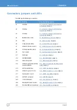
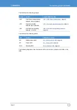
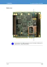
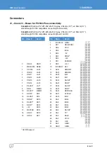
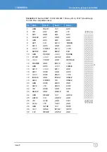
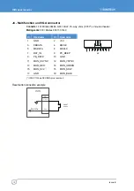
The ISIS has the following connectors:
Connector Function
Connector details in section
J1 ISA
Bus
J1, J2 and J3 - Buses for PC/104-Plus
connectivity
, page
J2 ISA
Bus
J1, J2 and J3 - Buses for PC/104-Plus
connectivity
, page
J3 PCI
Bus
J1, J2 and J3 - Buses for PC/104-Plus
connectivity
, page
J4 Multifunction,
VGA
J5 IDE
, page
J6 Video
(24-bit
LVDS)
, page
40.
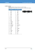
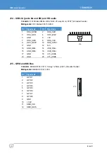
J7
USB 2.0 (Ports 2 and 3)
, page
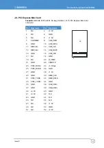
J8
PCI Express Mini Card
, page
41.
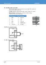
J9 Aux.
power
J9 - Auxiliary power connector
, page
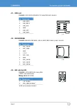
J11 SIM
card
, page
J12 SD/SDIO/MMC
, page
J13
IDE activity LED
, page
.
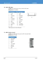
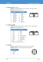
J14
USB 2.0 (ports 6A and 6B),
and HD AUDIO
J14 - USB 2.0 (ports 6A and 6B) and HD
audio
, page
43.
J15
GPIO and SM bus
, page
J16
USB 2.0 (ports 0,1,4,5)
J16 - USB 2.0 (ports 0, 1, 4, 5)
, page
J17
Serial ports 1 and 3
, page
45.
J18
GPS RF connector
, page
J20 10/100
Ethernet
, page
J22 Backlight
Inverter
control
J22 - Backlight inverter control
, page
.
J24
Remote SIM card (optional)
46.
Summary of Contents for ISIS XL-1.1-M512-F2G-GPS-I
Page 58: ...ISIS user manual Issue E 58 ...
Page 60: ...www eurotech com ...

