Operating Instructions
Modular Safety Control System MSC
20
(Translation of the original operating instructions) 2121331-04-04/19
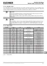
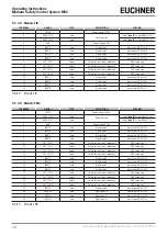
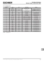
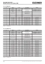
5.3.3.7. Module AC-FO4
TERMINAL
SIGNAL
TYPE
DESCRIPTION
VERSION
1
24 VDC
-
Power supply 24 VDC
-
2
NODE_SEL0
Input
Node selection
Input (
"type B"
as per EN 61131-2)
3
NODE_SEL1
Input
Input (
"type B"
as per EN 61131-2)
4
GND
-
Power supply 0 VDC
-
5
OSSD1_A
Output
Safety output 1
PNP active high
6
OSSD1_B
Output
PNP active high
7
RESTART_FBK1
Input
Feedback loop/restart 1
Input as per EN 61131-2
8
OUT_STATUS1
Output
Programmable digital output
PNP active high
9
OSSD2_A
Output
Safety output 2
PNP active high
10
OSSD2_B
Output
PNP active high
11
RESTART_FBK2
Input
Feedback loop/restart 2
Input as per EN 61131-2
12
OUT_STATUS2
Output
Programmable digital output
PNP active high
13
24 VDC
-
Power supply 24 VDC
24 VDC outputs, power supply*
14
24 VDC
-
15
GND
-
Power supply 0 VDC
0 VDC outputs*
16
GND
-
17
OSSD4_A
Output
Safety output 4
PNP active high
18
OSSD4_B
Output
PNP active high
19
RESTART_FBK4
Input
Feedback loop/restart 4
Input as per EN 61131-2
20
OUT_STATUS4
Output
Programmable digital output
PNP active high
21
OSSD3_A
Output
Safety output 3
PNP active high
22
OSSD3_B
Output
PNP active high
23
RESTART_FBK3
Input
Feedback loop/restart 3
Input as per EN 61131-2
24
OUT_STATUS3
Output
Programmable digital output
PNP active high
Table 7: Module AC-FO4
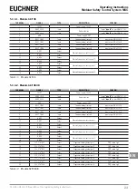
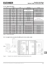
5.3.3.8. Module AC-FO2
TERMINAL
SIGNAL
TYPE
DESCRIPTION
VERSION
1
24 VDC
-
Power supply 24 VDC
-
2
NODE_SEL0
Input
Node selection
Input (
"type B"
as per EN 61131-2)
3
NODE_SEL1
Input
Input (
"type B"
as per EN 61131-2)
4
GND
-
Power supply 0 VDC
-
5
OSSD1_A
Output
Safety output 1
PNP active high
6
OSSD1_B
Output
PNP active high
7
RESTART_FBK1
Input
Feedback loop/restart 1
Input as per EN 61131-2
8
OUT_STATUS1
Output
State of the outputs 1A/1B
PNP active high
9
OSSD2_A
Output
Safety output 2
PNP active high
10
OSSD2_B
Output
PNP active high
11
RESTART_FBK2
Input
Feedback loop/restart 2
Input as per EN 61131-2
12
OUT_STATUS2
Output
State of the outputs 2A/2B
PNP active high
13
24 VDC
-
Power supply 24 VDC
24 VDC output, power supply*
14
n.c.
-
-
-
15
GND
-
Power supply 0 VDC
0 VDC output*
16
n.c.
-
-
-
Table 8: Module AC-FO2
* This terminal must be connected to the power supply so that the module functions correctly.
Summary of Contents for MSC
Page 1: ...EN Operating Instructions Installation and use Modular Safety Control System MSC ...
Page 171: ......
Page 173: ......

