


1
Operating Instructions
Safety Contact Expansion ESM-ES3..
Correct use
The Safety Contact Expansion ESM-ES3.. in combi-
nation with any safety relay from the EUCHNER ESM
series can be used to produce up to three additional
safety paths per device. An existing system can thus
be expanded practically indefinitely in a modular
manner. Activation takes place via a safety contact
of the safety relay; the ESM-ES3 provides monitor-
ing contacts for error monitoring. The devices can
be used in systems up to safety category 4, PL e
according to EN ISO 13849-1.
Before the device is used, a risk assessment must
be performed on the machine, e.g. according to the
following standards:
f
EN ISO 13849-1
f
EN ISO 12100
f
IEC 62061.
Correct use includes observing the relevant require-
ments for installation and operation, particularly
based on the following standards:
f
EN ISO 13849-1
f
EN 60204-1
f
IEC 62061.
Important!
f
The user is responsible for the integration of
the device in a safe overall system. For this
purpose, the overall system must be validated,
e.g. according to EN ISO 13849-2.
f
The device user must assess and document
remaining risks.
f
If a data sheet is included with the product, the
information on the data sheet applies.
Safety precautions
WARNING
f
Installation and setup of the device must be
performed only by authorized personnel.
f
Observe the country-specific regulations when
installing the device.
f
The electrical connection of the device is only
allowed to be made with the device isolated.
f
The wiring of the device must comply with the
instructions in these operating instructions,
otherwise there is a risk that the safety function
will be lost.
f
It is not allowed to open the device, tamper with
the device or bypass the safety devices.
f
All relevant safety regulations and standards are
to be observed.
f
The overall concept of the control system in
which the device is incorporated must be vali-
dated by the user.
f
Failure to observe the safety regulations can re-
sult in death, severe injuries and serious damage.
f
Note down the version of the device (see type la-
bel
Vx.x.x
) and check it each time prior to setup.
If the version changes, the use of the device in
the overall application must be validated again.
Features
f
3 safe, redundant relay outputs
1 auxiliary contact (error monitoring)
f
Activation via safety relay from the EUCHNER
ESM series
f
Modular, freely configurable safety system
f
Error monitoring by safety relay
f
Ground fault monitoring
f
Indication of the switching state via LED
f
Use up to PL e, SILCL 3, category 4
Function
The Safety Contact Expansion ESM-ES3.. in com-
bination with a safety relay from the EUCHNER
ESM series is designed for safe isolation of safety
circuits according to EN 60204-1 and can be
used up to safety category 4, PL e according to
EN ISO 13849-1.
Terminal
S11
(DC 24 V control voltage) is connected
with terminals
S15
and
S16
via the safety contacts
of the safety relay. Starting the safety relay also
activates the ESM-ES3... The safety relay discon-
nects the control voltage when the safety switch is
operated, and the safety contacts of the ESM-ES3..
open immediately.
If a fault occurs in the ESM-ES3.., this is detected by
the safety relay via terminals
S23
and
S24
.
Independent operation without safety relay is
not possible.
Fig. 1: Block diagram for ESM-ES3..
Mounting
As per EN 60204-1, the device is intended for in-
stallation in control cabinets with a minimum degree
of protection of IP54. It is mounted on a 35 mm
mounting rail according to DIN EN 60715 TH35.
Fig. 2: Mounting/removing
Electrical connection
f
When the 24 V version is used, a safety transform-
er according to EN 61558-2-6 or a power supply
unit with electrical isolation from the mains must
be connected.
f
External fusing of the safety contacts must be
provided.
f
A maximum length of the control lines of 1,000 m
with a conductor cross-section of 0.75 mm² must
not be exceeded.
f
The conductor cross-section must not exceed
2.5 mm².
f
If the device does not function after setup, it must
be returned to the manufacturer unopened. Open-
ing the device will void the warranty.
f
PE
(protective earth) must be connected to termi-
nal
S10
on the AC 115/230 V variant. Wiring of
the overall device is to be designed for 115/230 V.
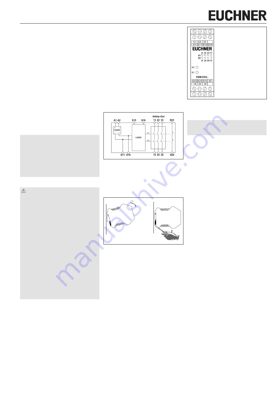
A1
Power supply
A2
Power supply
S11
DC 24 V control voltage
S10
Control line
S15
Control line
S16
Control line
S23
Error monitoring
S24
Error monitoring
13-14
Safety contact 1
23-24
Safety contact 2
33-34
Safety contact 3
Fig. 3: Connections
Setup procedure
Notice
The items listed under
must
be observed during setup.
1. Wiring ESM-ES3..:
Wire the ESM-ES3.. with the EUCHNER safety relay
according to your application (see Fig. 5 and Fig. 6).
2. Wiring safety relay:
Wire the safety relay according to the required
Performance Level determined (see operating
instructions for the safety relay).
3. Wiring feedback loop:
Wire the feedback loop as shown in Fig. 7 and Fig. 8.
4. Wiring power supply:
Connect the power supply to terminals
A1
and
A2
Attention:
Wiring only in de-energized state.
5. Starting the device:
Switch the operating voltage on.
Attention:
If the
Automatic start
behavior is set
on the safety relay, the safety contacts will close
immediately.
If the
Monitored manual start
behavior is set, close
the start button to close the safety contacts.
The LEDs
K1
and
K2
on the safety relay and on the
ESM-ES3.. illuminate.
6. Activating safety function:
Open the emergency stop circuit by actuating the
connected safety switch. The safety contacts of the
safety relay and the ESM-ES3.. open immediately.
7. Reactivating:
Close the emergency stop circuit. If
Automatic start
is selected on the safety relay, the safety contacts
will close immediately.
If the
Monitored manual start
behavior is set, close
the start button on the safety relay to close the safe-
ty contacts of the safety relay and the ESM-ES3...