


56
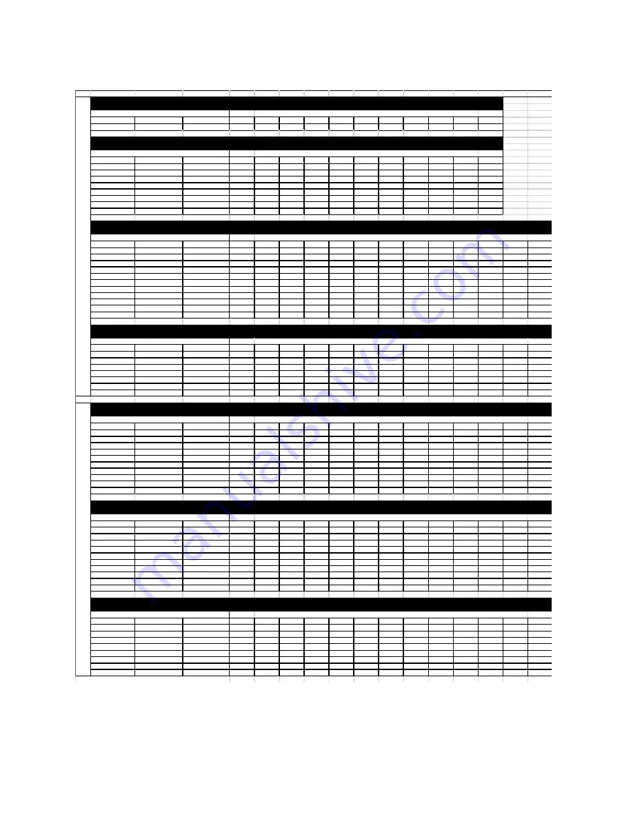
Pulley Combination Chart
Motor RPM
1725
1/3 to 1-1/2 HP
MOTOR PULLEY
Dd1
Dd2
Pd1
Pd2
AX BELTS
1VL34
1.9
2.9
2
3
Open
Closed
BLOWER PULLEY
DATUM DIAMETER
PITCH DIAMETER
5
4 1/2
4
3 1/2
3
2 1/2
2
1 1/2
1
1/2
0
AK114
11
11.2
308
323
339
354
370
385
400
416
431
447
462
1/3 to 2 HP
MOTOR PULLEY
Dd1
Dd2
Pd1
Pd2
AX BELTS
1VL40
2.4
3.4
2.6
3.6
Open
Closed
BLOWER PULLEY
DATUM DIAMETER
PITCH DIAMETER
5
4 1/2
4
3 1/2
3
2 1/2
2
1 1/2
1
1/2
0
AK114
11
11.2
400
416
431
447
462
477
493
508
524
539
554
AK94
9
9.2
488
506
525
544
563
581
600
619
638
656
675
AK79
7.5
7.7
582
605
627
650
672
694
717
739
762
784
806
AK66
6.2
6.4
701
728
755
782
809
836
863
889
916
943
970
AK54
5
5.2
863
896
929
962
995
1028
1062
1095
1128
1161
1194
AK46
4.2
4.4
1019
1059
1098
1137
1176
1215
1255
1294
1333
1372
1411
AK39
3.5
3.7
1212
1259
1305
1352
1399
1445
1492
1539
1585
1632
1678
AK32
3
3.2
1402
1455
1509
1563
1617
1671
1725
1779
1833
1887
1941
3 to 5 HP
MOTOR PULLEY
Dd1
Dd2
Pd1
Pd2
BX BELTS
2VP42
2.9
3.9
3
4
Open
Closed
BLOWER PULLEY
DATUM DIAMETER
PITCH DIAMETER
6
5 1/2
5
4 1/2
4
3 1/2
3
2 1/2
2
1 1/2
1
1/2
0
2BK160H
15.4
15.7
330
339
348
357
366
375
385
394
403
412
421
430
439
2BK140H
13.4
13.7
378
388
399
409
420
430
441
451
462
472
483
493
504
2BK120H
11.4
11.7
442
455
467
479
491
504
516
528
541
553
565
577
590
2BK110H
10.4
10.7
484
497
511
524
537
551
564
578
591
605
618
631
645
2BK100H
9.4
9.7
534
548
563
578
593
608
622
637
652
667
682
697
711
2BK90H
8.4
8.7
595
611
628
644
661
677
694
710
727
744
760
777
793
2BK80H
7.4
7.7
672
691
709
728
747
765
784
803
821
840
859
877
896
2BK70H
6.4
6.7
772
794
815
837
858
880
901
923
944
965
987
1008
1030
2BK60H
5.4
5.7
908
933
958
984
1009
1034
1059
1084
1110
1135
1160
1185
1211
2BK55H
4.9
5.2
995
1023
1050
1078
1106
1133
1161
1189
1216
1244
1272
1299
1327
2BK50H
4.4
4.7
1101
1132
1162
1193
1223
1254
1285
1315
1346
1376
1407
1438
1468
7-1/2 to 10 HP
MOTOR PULLEY
Dd1
Dd2
Pd1
Pd2
BX BELTS
2VP60
4.3
5.5
4.7
5.9
Open
Closed
BLOWER PULLEY
DATUM DIAMETER
PITCH DIAMETER
6
5 1/2
5
4 1/2
4
3 1/2
3
2 1/2
2
1 1/2
1
1/2
0
2BK160H
15.4
15.7
516
527
538
549
560
571
582
593
604
615
626
637
648
2BK140H
13.4
13.7
592
604
617
630
642
655
667
680
693
705
718
730
743
2BK120H
11.4
11.7
693
708
722
737
752
767
781
796
811
826
840
855
870
2BK110H
10.4
10.7
758
774
790
806
822
838
854
871
887
903
919
935
951
2BK100H
9.4
9.7
836
854
871
889
907
925
943
960
978
996
1014
1031
1049
2BK90H
8.4
8.7
932
952
972
991
1011
1031
1051
1071
1091
1110
1130
1150
1170
2BK80H
7.4
7.7
1053
1075
1098
1120
1143
1165
1187
1210
1232
1255
1277
1299
1322
3 to 5 HP
MOTOR PULLEY
Dd1
Dd2
Pd1
Pd2
BX BELTS
2VP42
2.9
3.9
3
4
Open
Closed
BLOWER PULLEY
DATUM DIAMETER
PITCH DIAMETER
6
5 1/2
5
4 1/2
4
3 1/2
3
2 1/2
2
1 1/2
1
1/2
0
2B5V278
27.8
28.1
184
189
194
200
205
210
215
220
225
230
235
240
246
2B5V250
25
25.3
205
210
216
222
227
233
239
244
250
256
261
267
273
2B5V234
23.4
23.7
218
224
230
237
243
249
255
261
267
273
279
285
291
2B5V200
20
20.3
255
262
269
276
283
290
297
304
312
319
326
333
340
2B5V184
18.4
18.7
277
284
292
300
307
315
323
331
338
346
354
361
369
2B5V160
16
16.3
317
326
335
344
353
362
370
379
388
397
406
414
423
2B5V154
15.4
15.7
330
339
348
357
366
375
385
394
403
412
421
430
439
2B5V136
12.6
12.9
401
412
423
435
446
457
468
479
490
501
513
524
535
2B5V124
12.4
12.7
407
419
430
441
453
464
475
487
498
509
521
532
543
2B5V110
11
11.3
458
471
483
496
509
522
534
547
560
572
585
598
611
7-1/2 to 10 HP
MOTOR PULLEY
Dd1
Dd2
Pd1
Pd2
BX BELTS
2VP60
4.3
5.5
4.7
5.9
Open
Closed
BLOWER PULLEY
DATUM DIAMETER
PITCH DIAMETER
6
5 1/2
5
4 1/2
4
3 1/2
3
2 1/2
2
1 1/2
1
1/2
0
2B5V278
27.8
28.1
289
295
301
307
313
319
325
331
338
344
350
356
362
2B5V250
25
25.3
320
327
334
341
348
355
361
368
375
382
389
395
402
2B5V234
23.4
23.7
342
349
357
364
371
378
386
393
400
408
415
422
429
2B5V200
20
20.3
399
408
416
425
433
442
450
459
467
476
484
493
501
2B5V184
18.4
18.7
434
443
452
461
470
480
489
498
507
517
526
535
544
2B5V160
16
16.3
497
508
519
529
540
550
561
571
582
593
603
614
624
2B5V154
15.4
15.7
516
527
538
549
560
571
582
593
604
615
626
637
648
2B5V136
12.6
12.9
628
642
655
669
682
695
709
722
735
749
762
776
789
2B5V124
12.4
12.7
638
652
666
679
693
706
720
733
747
761
774
788
801
2B5V110
11
11.3
717
733
748
763
779
794
809
824
840
855
870
885
901
15 to 20 HP
MOTOR PULLEY
Dd1
Dd2
Pd1
Pd2
BX BELTS
2VP75
5.8
7
6.2
7.4
Open
Closed
BLOWER PULLEY
DATUM DIAMETER
PITCH DIAMETER
6
5 1/2
5
4 1/2
4
3 1/2
3
2 1/2
2
1 1/2
1
1/2
0
2B5V278
27.8
28.1
381
387
393
399
405
411
417
424
430
436
442
448
454
2B5V250
25
25.3
423
430
436
443
450
457
464
470
477
484
491
498
505
2B5V234
23.4
23.7
451
459
466
473
480
488
495
502
509
517
524
531
539
2B5V200
20
20.3
527
535
544
552
561
569
578
586
595
603
612
620
629
2B5V184
18.4
18.7
572
581
590
600
609
618
627
636
646
655
664
673
683
2B5V160
16
16.3
656
667
677
688
698
709
720
730
741
751
762
773
783
2B5V154
15.4
15.7
681
692
703
714
725
736
747
758
769
780
791
802
813
2B5V136
12.6
12.9
829
842
856
869
883
896
909
923
936
949
963
976
990
** 2HP Motors on 20 IN Blowers use 2VP42 Pulleys
10
- 20
I
N
. B
LO
W
ER
**
TURNS ON MOTOR PULLEY
25
I
N
. B
LO
W
ER
TURNS ON MOTOR PULLEY
TURNS ON MOTOR PULLEY
TURNS ON MOTOR PULLEY
TURNS ON MOTOR PULLEY
TURNS ON MOTOR PULLEY
TURNS ON MOTOR PULLEY
Summary of Contents for MUA Controls
Page 82: ...82 Notes ...
Page 83: ...83 CLEANING MAINTENANCE RECORD Date Service Performed ...


