Copyright 201
9
EtherWAN Systems, Inc.
Page 1
All Rights Reserved
EW75000
10/8/
20
19
W70G-EW75000Q1
EW75000 Hardened Wireless LAN Access Point / Subscriber Unit
Installation Guide
1
Unpacking
Open the carton and unpack the items. Your package should include:
One EW75000 hardened wireless access point (AP) or subscriber unit
Zero, two or four omnidirectional antennas, depending on model
Mounting bracket set
Quick installation guide
If any items are missing or damaged, notify your EtherWAN
representative.
2
Supplying Power
All EW75000 series models are PoE Powered Devices, and have no AC or
DC power socket. Power is supplied through an Ethernet cable plugged
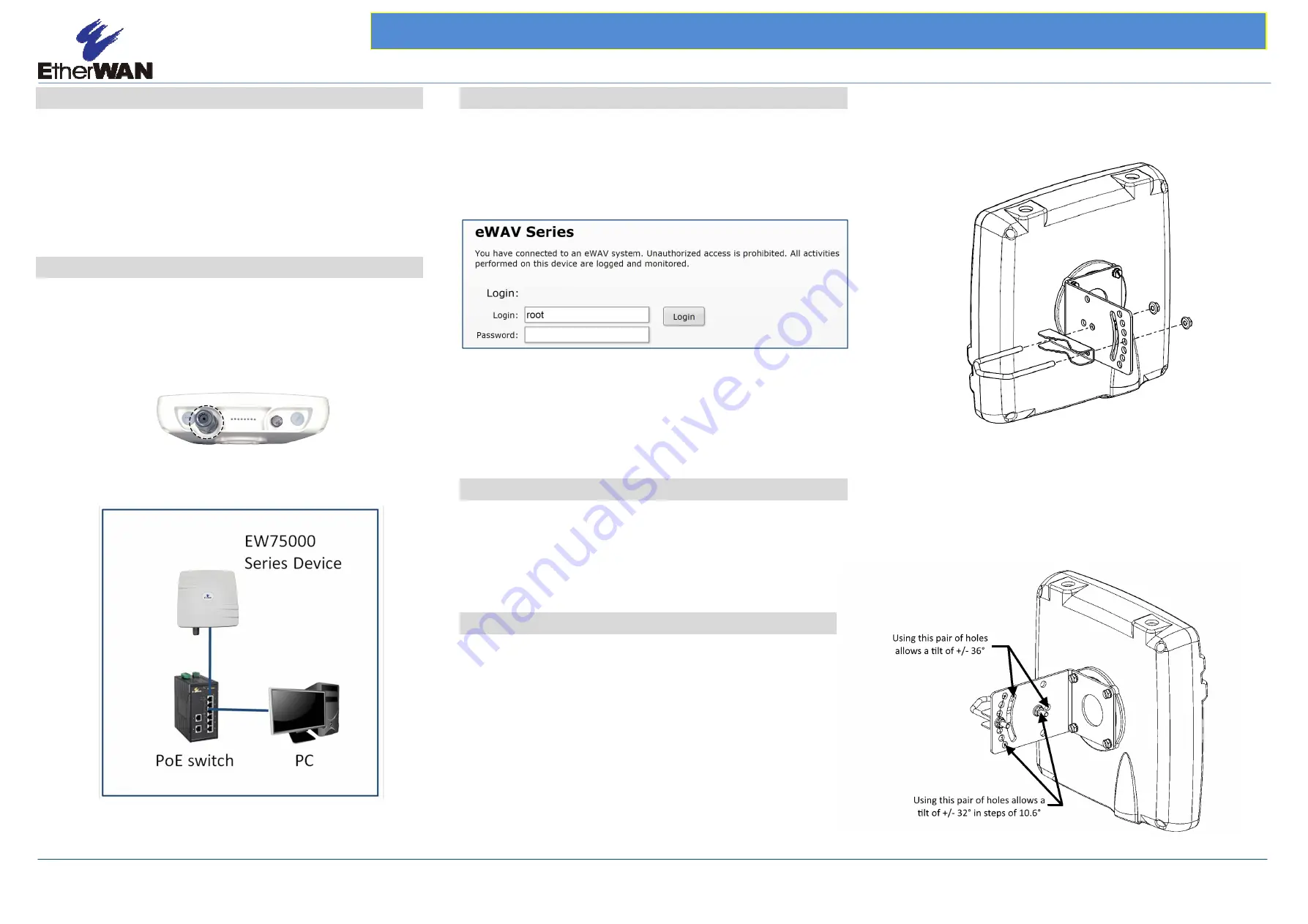
into the RJ45 port (shown in figure below). The cable must be connected
to a switch that supports PoE, or an inline power injector. Maximum
power consumption is 13 watts.
3
Digital Configuration
Use an Ethernet cable to connect a PC to the PoE switch or power
injector, and another cable to connect the switch/injector to the
EW75000. Use a web browser to navigate to the default IP address, and
log in.
The default IP address is 192.168.1.20
User name is
root
, no password.
The Quick Set page will display by default. Select the function mode from
the drop-down menu in the upper right corner. The fields displayed
depend on the mode selected. Alternatively, you can exit the Quick Set
page by clicking the “
Advanced Mode
” tab in the upper right corner, and
going directly to the main screen.
4
Connect Antennas
Depending on the model, your device may be equipped with an internal
directional antenna, which provides long-distance coverage in the
direction it is pointing. Some models include two 5 GHZ and/or two
2.4GHz omnidirectional antennas. Screw the antennas into the
corresponding threaded sockets in the housing.
5
Physical Installation
NOTE
: It is recommended to test all wireless devices before final
installation. This includes bench testing, and signal testing of the AP and
subscriber unit in the positions where they will be mounted. Loosely
mount AP and subscriber units in the intended installation spots, and
ensure that the transmission signal is strong enough for the intended
application.
This product is designed for outdoor installation on a pole or wall. It is
recommended to install the AP at a height of at least 5 meters (15 feet).
A higher mounting position will result in a stronger signal. Make sure that
there are no obstacles between devices. Mount the AP with the Ethernet
port and LED facing down.
1.
Align the four holes on the housing bracket with those on the back
face of the housing, and use the four screws
and lock washers
to
attach the bracket to the housing.
2. Attach the bracket with the supplied screws as shown in figure
below. Make sure the stop tabs (indicated by dotted circles in
figure) are on the same side as the arc-shaped slot.
Pole
mounting:
Position the Wireless unit and mount on the pole. Use the supplied U-Bolt
and position the Wireless unit as shown in the graphic below. Once the
Wireless unit is in position, tighten the supplied nuts with washers to the
U-Bol
t
until the Wireless unit is securely attached to the pole.
RJ-45 PoE Port


