


ETEL Doc. - Operation & Software Manual # DSC2P 903 / Ver. F / 3/6/05
Chapter A: Internal functioning & architecture
Operation & Software Manual
Direct Drives & Systems
19
2.
Current references generator
The motor has to deliver a force F = F
c
independently of its position with respect to the
magnets poles. All phases must then be fed with
sinusoidal type currents, in phase with the
magnetic field. For a three-phase motor, 3
sinusoidal currents must have a 120
o
phase-shift
(for a two-phase motor, it has to be a 90
o
phase-
shift). Three phases motor will be considered, as it
is the most commonly used. The
current
reference generator
multiplies first the force
reference F
c
by the motor position on the sinusoid,
making out reference currents:
I
c1
= sin (X + 0
o
) in phase 1,
I
c2
= sin (X + 120
o
)
in
phase 2 and
I
c3
= sin (X + 240
o
)
in phase 3.
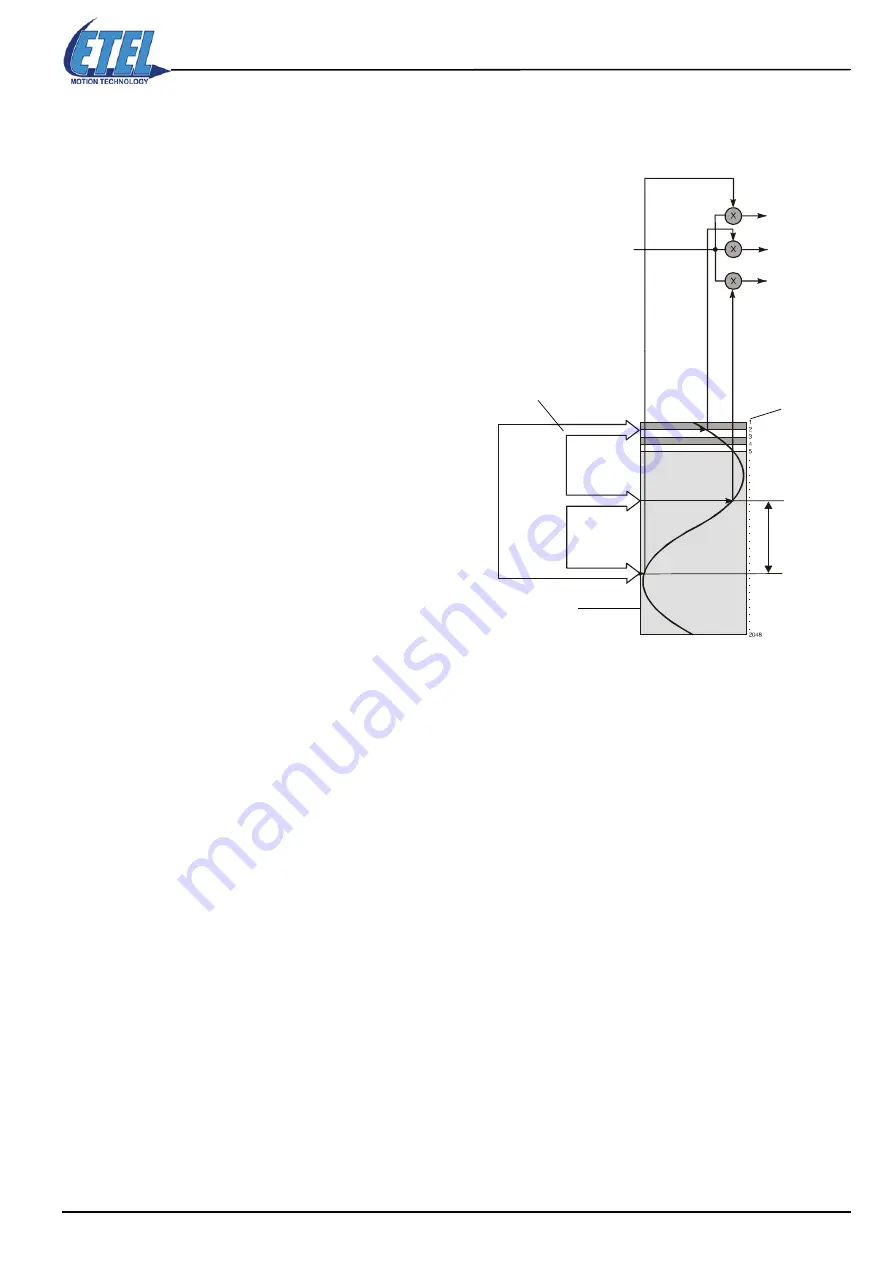
The motor currents calculation is as follows:
Three pointers (1), with a 120
°
electrical phase-
shift, point at in a table, according to the motor
position. This table, called
commutation look-up
table
(2), contains 2048 points (3) forming a
sinusoidal function period. Motor position sine-
forms are thus immediately read on the numbers of
the table. The force F
c
is then multiplied by each of
the two values giving I
c1,
I
c2
and I
c3
.
Remark:
When one of the pointers reaches the end of the table, it goes on from the other end.
Pointing at the right places in the table when powering on the motor is important, because its position with
respect to the magnets is not known at the beginning. The
initialization
procedure allows the user to know the
initial position.
Current references generator
F
c
I
c1
I
c2
Sinusoid cur
rent shape 1
Motor
position
(1)
(2)
(3)
12
0 °
Sin. cur
rent shape 3
I
c3
Sinusoid cur
rent shape 2


