Irideon Control Installation and User Manual
29
Product Detail
The following is product detail that may be a useful resource during power
up and system test for your specific control product. For luminaire power
up and system test procedures please refer to the appropriate luminaire
user’s guide.
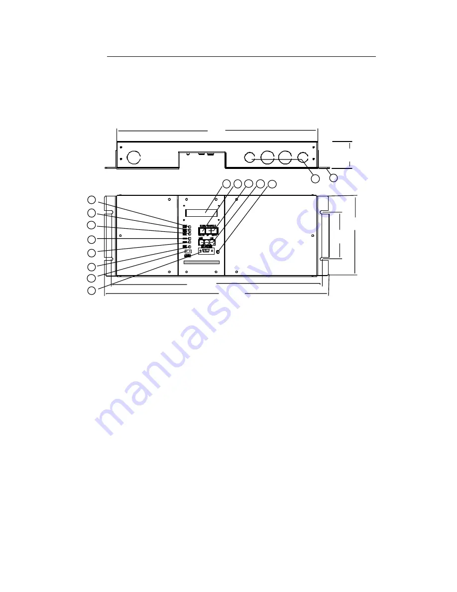
Master Control Processor - detail
1. DEVICE COM. - LED indicating data transmission between the MCP
and the luminaires.
2. CONTROL COM. - LED indicating data transmission between the
MCP and Remote Control Station or the PC.
3. AUX. COM. - LED indicating data transmission between the MCP
and DMX devices.
4. 5VDC - LED indicating the presence of DC logic voltage for control
electronics (internal power supply working properly).
5. 24VDC - LED indicating the presence of DC voltage to operate
Remote Control Stations (internal power supply working
properly).
6. TEST MODE - LED indicating MCP TEST MODE SWITCH is in test
position.
7. TEST MODE SWITCH - Initiates self test of luminaire control.
8. PC Connect - DB9 Receptacle for PC connection.
9. Clock / Calendar Display - LCD showing Day, Date and Time.
14
15
2.30"
(58mm)
17.00"
(432 mm)
1
2
3
6
7
8
9
10
11
5
4
12
13
4.00"
(102mm)
6.80"
(173mm)
17.875"
(454mm)
19.00"
(483mm)
Summary of Contents for IRIDEON
Page 10: ...6 Introduction This page intentionally blank...
Page 44: ...40 System Test This page intentionally blank...
Page 50: ...46 Troubleshooting This page intentionally blank...
Page 60: ...56 Maintenance This page intentionally blank...
Page 64: ...60 Software Hardware Components This page intentionally blank...
Page 70: ...66 Astronomical Time Clock installation instructions This page intentionally blank...
Page 83: ...Irideon Control Installation and User Manual 79 This page intentionally blank...


