5.13.
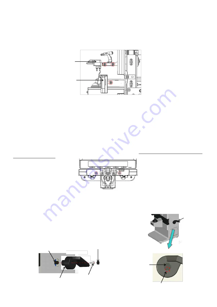
PD plate assy. ALM700
Remove the back cover (Refer to ‘4. Assembly and Disassembly of External Facing’.)
Disconnect the harness of the control board which is connected to the PD Assy. (Only for ALM700, control board
side: CN11)
Remove the marking/ retention unit Assy.
Remove the lens plate and replace it with new one after unscrewing both sides of 2 screws (cross-recessed bind
screw M3×8 black).
It is necessary to adjust the lengthwise position at the time of attaching the marking/ retention unit Assy. Attach
the marking/ retention unit so that the lens retention pin is positioned in the center of the light receiving unit.
Check the marking position by measuring the cylinder lens of the maintenance lens set. Confirm that the
marking matches with the fiducial of cylindrical lens (Refer to ‘5-8 Marking Pen, Retention Pin, marking/
Retention Unit Assy.’)
5.14.
Nose pad assy.
Remove the insulation stickers and unscrew 2 screws (low head precision screw FX-0230EB) fixing the nose pad
Assy. after pulling out the lens plate.
(The insulation sticker is included in the repair parts of “nose pad Assy.”.) Note: The screws are the special ones.
Please do not loose them.
5.15.
LP lever
Remove the screw hiding on the PD lever by inserting the skinny
tool such as tweezers in the hole for removing the screw hiding.
After removing the screw hiding, replace the LP lever by
unscrewing 1 screw fixing the LP lever (cross-recessed bind screw
M3×8) and pulling it out.
At the time of reassembling, insert the LP lever with attention to
the direction because D cut is provided at the shaft.
Marking/Retention
Unit assy.
PD plate assy
(ALM700)
LP lever
Screw hiding
D cut
LP lever
Cross-recessed bind screw
M3x3
Screw hiding
Hole for removing
screw hiding
Summary of Contents for ALM 700
Page 1: ...Maintenance manual Auto Lensmeter ALM700 V1 10 2016...
Page 36: ......


