background image

5.9.


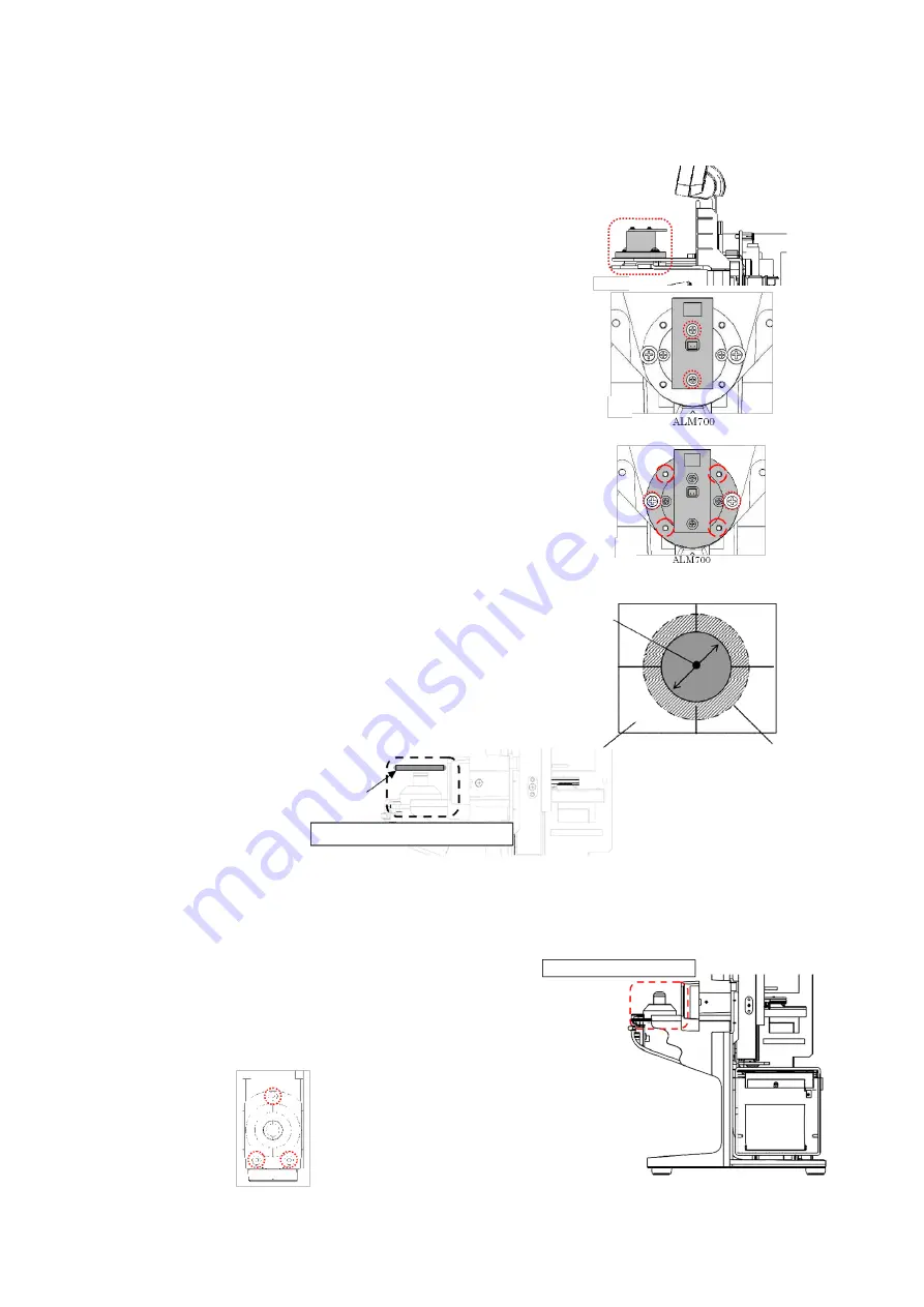
Light projecting unit assy.  

 
Remove the back cover and top cover. 
(Refer to ‘4. Assembly and Disassembly of External Facing’.) 
 

1)


Replacement of Measurement Light Board Assy. 
Unscrew 2 screws (cross-recessed bind screw M2×L6 black) 
fixing  the  measurement  light  board Assy.,  and  place  the 
replacement  measurement light board Assy. roughly in the 
center. 
After  that,  place  each  cover  and  perform  calibration. 
(Refer to ‘8. Calibration’.) 


[Fig.1] 

2)


Replacement of Light Projecting Unit Assy. 
Unscrew 2  screws (cross-recessed  bind  screw (P3)  M3×10 
black),  and  place  the  replacement  light  projecting  unit 
Assy.  temporarily. :Fig. 2 
Then,  align  with  the  optical  axis  of  the  light  receiving 
Assy. by  using 4 M3 set screws. 

Adjustment Criteria

】 

Place  the  perforated  screen  on  the  light  receiving  unit 
Assy.  Confirm  visually  that  the  scribing  line  and  light 
from the light  projecting unit match. :Fig. 3 


[Fig.2] 


5.10.


Light receiving unit assy. 

 
Remove the light receiving unit cover. 
(Refer  to  ‘4-4.  Removal  of  Light  Receiving  Unit  Cover’.) 
Remove 3 screws (hexagonal socket cap low head bolt M3×6) 
fixing the light receiving unit and harnesses connected, and 
place  the  replacement  light  receiving unit Assy.  roughly  in 
the  center. 


Light projecting unit assy. 

Lens stand aperture (

φ6)


Perforated screen 

Scribing line 
ALM700: 

φ13


Perforated screen 

Light receiving unit assy. 

Light receiving unit assy. 

Summary of Contents for ALM 700

Page 1: ...Maintenance manual Auto Lensmeter ALM700 V1 10 2016...

Page 2: ...parts 8 5 1 Control board assy 8 5 2 Printer Control Board Assy and Printer 8 5 3 LCD assy 9 5 4 Switching power supply 10 5 5 Power supply inlet 10 5 6 Power supply switch 11 5 7 Memory switch board...

Page 3: ...External diagram Utility box PD plate assy Utility box cover Top cover Back cover Nose pad assy LP lever Printer cover unit Light receiving unit cover Front cover Power supply switch Power supply inle...

Page 4: ...latch LCD assy Light projecting unit assy Marketing Retention unit Assy Nose pad assy Light receiving unit assy Switching power supply Printer assy Terminal unit assy LP lever Mechanical unit assy Con...

Page 5: ...trol board assy only for ALM700 Flat cable Red Brown 1 4 PD assy PD sensor board assy PD position sensor board Memory switch board assy CMOS camera board To terminal unit FG green yellow Printer contr...

Page 6: ...crews cross recessed bind head tapping screw 3 8 black shown on the Fig 1 cover is removed Fig 1 3 Unscrew the screws fixing the back cover Unscrew 2 screws cross recessed bind screw M3 8 on the upper...

Page 7: ...the LCD Assy Fig 3 2 Remove the LCD Assy by unscrewing the screws hexagon socket cap low head bolt M3 6 black fixing the LCD Assy Fig 3 Fig 3 4 3 Removal of top cover Remove the top cover by unscrewi...

Page 8: ...y 3 Replace the printer by unscrewing 2 screws cross recessed bind head tapping screw 3 10 black fixing it Fig 1 4 Replace the thermal head of the printer Disconnect the harness on the side of the pri...

Page 9: ...ews cross recessed bind head tapping screw 3 8 fixing the LCD Fig 2 Fig 1 Fig 2 3 Replacement of LCD Top Cover Protection Plate LCD unit ALM700 The LCD top cover protection plate and operation switch...

Page 10: ...switching power supply Replace it by unscrewing 2 screws cross recessed bind screw M3 5 fixing the switching power supply 5 5 Power supply inlet Remove the back cover Refer to 4 Assembly and Disassemb...

Page 11: ...Remove the power supply switch by pressing the click Fig 3 Replace the harnesses of the power supply switch and power supply switch Fig 3 replacement of harnesses Fig 1 Fig 2 5 7 Memory switch board a...

Page 12: ...ent by placing 5D cylindrical lens with contacting with the lens plate in the direction of AX 180 At this time adjust the marking unit so as that the marking is on the fiducial line Then perform align...

Page 13: ...ng unit Assy temporarily Fig 2 Then align with the optical axis of the light receiving Assy by using 4 M3 set screws Adjustment Criteria Place the perforated screen on the light receiving unit Assy Co...

Page 14: ...mbly and Disassembly of External Facing Then remove the LCD retention BKT by unscrewing 4 screws cross recessed bind screw M4 6 fixing it Fig 1 Remove the FGs screwed on measurement light board Assy C...

Page 15: ...of cylindrical lens Refer to 5 8 Marking Pen Retention Pin marking Retention Unit Assy 5 14 Nose pad assy Remove the insulation stickers and unscrew 2 screws low head precision screw FX 0230EB fixing...

Page 16: ...ue exceeds the upper limit of measurement range 9 CYL Over CYL measurement value exceeds the upper limit of measurement range 10 Prism Over Prism measurement value exceeds the upper limit of measureme...

Page 17: ...is dirty Wipe the lens with the soft cloth with taking care not to scratch it Refer to 9 2 Optical Unit 9 Cleaning Replace the measurement light board Assy Refer to 5 9 Light Projecting Unit Assy Mea...

Page 18: ...et correctly Printer Cover Opened is still displayed No Yes Yes Replace printer assy Replace control board Set the cover correctly and cycle the power No Normal Printer Overheated is displayed Printer...

Page 19: ...f the device Take a measurement of the lens which degree is within the measurement range of the device No EEPROM Failure is displayed EEPROM Failure is still displayed even after cycling power Yes Rep...

Page 20: ...se a measurement image cannot be detected Check the lens to be measured and take a measurement again Measurement Error is displayed The light receiving unit is exposed to the direct sunlight or strong...

Page 21: ...ement screen 11 Err is displayed on display area of UV transmittance measurement value In case that there is abnormality on main control board Yes Normal The symptom is improved after cycling power Me...

Page 22: ...logo is displayed until the comment as shown below appears 7 2 Confirmation procedure of measurement image 1 Menu screen is displayed when entering the dealer mode 2 Select 2 Freeze Image with and dis...

Page 23: ...at the lens to be measured is dirty or scratched or the lens under the lens holder is dirty If something blocks a part of the light path Measurement ring lacks Measurement value is unstable Measuremen...

Page 24: ...h of vertical and horizontal brightness of measurement image Displaying max min of the brightness of measurement image and its direction angle Run Displaying measurement image in real time Out Outputt...

Page 25: ...rs 8 2 Device setting Check the setting of function Menu screen is displayed when entering the dealer mode Select 3 Function with and check the setting by displaying the setting screen with Setting sc...

Page 26: ...m powers 18 16 P 10 10 00 Calibration of 10 prism powers 19 17 Far pt 0 30 standard value Progressive lens calibration value of far point 1 20 18 Near pt 0 38 standard value Progressive lens calibrati...

Page 27: ...rection and Y direction becomes 0 00 When the prism value reaches between 0 00 and 0 01 in both X and Y directions the spherical value is automatically calibrated to the value of the test lens Input t...

Page 28: ...input 5 Calibration of prism Calibration of 2 and 5 2 is not included in the maintenance lens set Input the test values with Align the prism lens so that the base direction becomes 0 The prism value i...

Page 29: ...sing 7 Adjustment of optical end of papillary distance PD value Place the jig for adjusting PD center position against the PD plate as shown on the diagram Place the jig for adjusting PD center positi...

Page 30: ...the MENU screen by pressing on the measurement screen Select 1 Setting on the MENU screen and display the Setup screen by pressing Select Step on the Setup screen with and set as 0 01 with Switch to t...

Page 31: ...r for cleaning Clean carefully not to damage the surface of optical parts When the surface is damaged measurement may not be carried out successfully Clean the part pointed in the illustration below C...

Page 32: ...rsion of the lensmeter to be changed Example of RS 232C connection D Sub 9pin male D Sub 9pin female Lensmeter Connection PC 1 1 2 2 3 3 4 4 5 5 6 6 7 7 8 8 9 9 10 2 Change procedure 1 Connection betw...

Page 33: ...at the time of activating the program mode is 115200bps Usually it is not necessary to change this setting 4 Setting of PC Activate ComUpdate by double clicking it The software as shown below is acti...

Page 34: ...n the screen Set as On Match with the value set on 3 Set as ALM700 Select the COM port to be used by clicking the up down button and execute it by clicking on the port No CAUTIONS AT THE TIME OF WRITI...

Page 35: ...ivated by pressing the ADD Memory switch after writing the software The software version can be checked by outputting the calibration value on 1 Output Adjust of 4 Memory on the MENU screen after star...

Page 36: ......

Reviews: