Art. No. 11162
All rights reserved. Reproduction as well as electronic duplication of this user guide, complete or in part, requires the written consent of
ESERA GmbH. Errors and technical modification subject to change.
ESERA GmbH, ESERA-Automation 2020
www.esera.de
11162 V2.0 R1.0 Manual
Page 3 von 5
6
Assignment RJ45 socket (input/output)
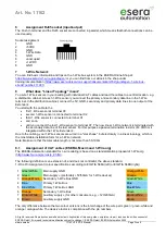
The Push In terminal and the RJ45 socket are connected in parallel, which means that both connections can be
used equally.
Socket assignment
1
GND
2
+5VDC
3
GND
4
1-Wire Data
5
GND
6
unoccupied
7
+12VDC
8
GND
7
1-Wire Network
You can find basic information and tips on the 1-Wire bus system in the ESERA Online Shop at:
https://www.esera.de/1-wire-grundlagen/
or you can find from our eBook in the shop under
training/documentation (
https://www.esera.de/service-support/dokumentation/352/grundlagen-1-wire-bus-
8
What does "Linear Topology" mean?
You wire 1-Wire sensors in your building with individual CAT cables and lead the cables to a central location, e.g.
a distribution cabinet. At each 1-Wire sensor you connect the primary and secondary data line in the 1-Wire
terminal. In the distribution cabinet, connect the 5V, GND, secondary and primary data lines to one output of the
Extender 4.
You start with the cable to the
first 1-Wire sensor at terminal X3
second 1-Wire sensor is connected to terminal X2
third 1-Wire sensor is connected to terminal X1
and so on
until you connect the last 1-Wire sensor to terminal X7. The now linear 1-Wire network is terminated with
the secondary data line of the last sensor. For this purpose a passive termination resistor of 4.7kOhm is
integrated within the 1-Wire Extender 4.
Due to the cabling, your 1-Wire sensors are wired in a "star shape", but electrically in a linear topology, which is
the most stable installation form for a 1-Wire network.
Note: Make sure that the total cable length is not more than 50-100m.
8.1 Assignment of CAT cables (ESERA, Maxim and 1-Wire.org)
The ESERA-Automation standard for 1-wire cabling is based on a standardization proposal of 1-Wire.org
(
http://www.1wire.org/en-us/p_2.html
).
The following definition is an extension of, and does not contradict, the above standard.
1-Wire Pin Assignment (colour specifications according to EIA/TIA 568A (left) or EIA/TIA 568B (right))
1 Green/White
Main supply GND
Orange/White
2 Green
Main (pref5V/50mA for 1-Wire devices)
Orange
3 Orange/White
Secondary 1-Wire Bus GND
Green/White
4 Blue
Primary 1-Wire Bus
Blue
5 Blue/White
Primary 1-Wire Bus GND
Blue/White
6 Orange
Secondary 1-Wire Bus
Green
7 Brown/White
Auxiliary (for other consumers, e.g. +12V/200mA)
Brown/White
8 Brown
Auxiliary supply GND
Brown
The only difference between the two colour versions is the interchange of the wire pairs green / green-white and
orange / orange-white. The decisive factor is compliance with the pin numbers.


