background image

Edition 030411

– 6 –

d1s325

XS1

Connector, 23–pol. Connnection for the wire feed unit

XS2 – 4

Main welding current contact, single pole

XT1

3 – pole terminal block

XT2

9 – pole terminal block

Summary of Contents for ESABMig 325

Page 1: ...0349 300 037 Valid for serial no 226 xxx xxxx 030411 ESABMig 325 Service manual ...

Page 2: ...on 9 AP2 2 Connections to the digital instrument 10 SERVICE INSTRUCTIONS 11 What is ESD 11 INSTRUCTIONS 12 SAFETY 12 INSTALLATION 13 Placing 13 Assembly of components 13 Assembly of stabilizer 14 Electrical installation 14 Mains power supply 15 OPERATION 16 Connection and control devices 16 FUNCTIONS EXPLANATION 17 Overheating protection 17 Inductance connection 17 MAINTENANCE 17 Inspection and cl...

Page 3: ... component description This manual contains details of all design changes that have been made up to and including August 2002 The ESABMig 325 is designed and tested in accordance with international and European standard IEC EN 60974 1 and EN 50199 On completion of service or repair work it is the responsibility of the person s etc performing the work to ensure that the product does not depart from...

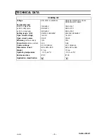
Page 4: ... cycle 320 A 30 V 320 A 30 V Setting range DC 40A 16V 320A 30V 40A 16V 320A 30V Open circuit voltage 16 40 V 16 40 V Open circuit power 200 W 200 W Efficiency at max current 75 75 Power factor at max current 0 94 0 94 Control voltage 42 V 50 60 Hz 42 V 50 60 Hz Dimensions lxwxh 840 x 425 x 830 840 x 425 x 830 Weight 111 kg 111 kg Operating temperature 10 to 40oC 10 to 40oC Enclosure class IP 23 IP...

Page 5: ...utout KM1 Main contactor 42V 50 60Hz L1 Inductor AP2 Digital instrument accessory QF1 Switch ON OFF R1 Resistor R2 Varistor RS1 Shunt accessory SA1 4 step switch coarse selection of welding voltage SA2 10 step switch fine selection of welding voltage ST1 Thermal overload cutout opens at 120oC Mounted at the cooling fins of the diode bridge ST2 Thermal overload cutout opens at 130oC Mounted in the ...

Page 6: ...Edition 030411 6 d1s325 XS1 Connector 23 pol Connnection for the wire feed unit XS2 4 Main welding current contact single pole XT1 3 pole terminal block XT2 9 pole terminal block ...

Page 7: ...Edition 030411 7 d1s325 ESABMig 325 400 415V ...

Page 8: ...Edition 030411 8 d1s325 ESABMig 325 230 500V ...

Page 9: ...ess simultaneously both pushbuttons placed on the meter PC board In sequence symbols of the calibration modes appear U voltage calibration I current calibration dU voltage correction Release the buttons as the required mode appears 3 Adjust the voltage or the current value equal to the value shown by the reference meter by means of the pushbuttons S1 S2 Voltage calibration mode The reference meter...

Page 10: ...Edition 030411 10 d1s325 AP2 2 Connections to the digital instrument ...

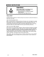
Page 11: ...tricity is prevented from building up on you or on anything at your work station then there cannot be any static discharges Nonconductive materials e g fabrics or insulators e g plastics generate and hold static charge so you should not bring unnecessary nonconductive items into the work area It is obviously difficult to avoid all such items so various means are used to drain off any static discha...

Page 12: ...ng equipment must be familiar with S its operation S location of emergency stops S its function S relevant safety precautions S welding 2 The operator must ensure that S no unauthorised person is stationed within the working area of the equipment when it is started up S no one is unprotected when the arc is struck 3 The workplace must S be suitable for the purpose S be free from draughts 4 Persona...

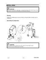
Page 13: ...o interference It is the user s responsibility to take adequate precautions Placing Position the welding power source so that its cooling air inlets and outlets are not obstructed Assembly of components During transport the rear wheels of the power source are in their forward position Before use place the wheels in their rear position WARNING ...

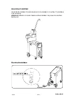
Page 14: ...of stabilizer Assemble the stabilizer if counter balance is to be installed on machine The stabilizer is an accessory Attention Utilization of counter balance without stabilizer may cause the machine tipping over Electrical installation ...

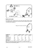
Page 15: ... 3 50 Hz 3 50 60 Hz 3 50 Hz 3 60 Hz 3 60 Hz Voltage V 230 400 415 500 230 440 460 Current A at100 duty cycle 16 9 7 16 8 at 60 duty cycle 23 14 10 23 12 at 30 duty cycle 35 20 16 34 18 Cable area mm2 4 x 4 4 x 2 5 4 x 2 5 4 x 4 4 x 2 5 Fuse slow A 20 16 16 20 16 NB The mains cable areas and fuse sizes as shown above are in accordance with Swedish regulations They may not be applicable in other cou...

Page 16: ...ns more than 10o In that case appropriate securing has to be provided Connection and control devices 1 Mains supply switch 7 Connection for return cable high induc tance 2 Switch precise control 8 Connection for return cable low induc tance 3 Switch coarse control 9 Connection for welding current cable 4 Indicating lamp power supply ON 10 Connection for control cable for wire feeder 5 Orange indic...

Page 17: ...knowledge authorised personnel may remove the safety plates Note All guarantee undertakings from the supplier cease to apply if the customer himself attempts any work in the product during the guarantee period in order to rectify any faults Inspection and cleaning Check regularly that the power source is free from dirt The power source should be regularly blown clean using dry compressed air at re...

Page 18: ... 18 notes NOTES ANTECKNINGAR ...

Page 19: ... 19 notes ...

Page 20: ... 20 notes ...

Page 21: ...nternational AB Gothenburg Tel 46 31 50 90 00 Fax 46 31 50 93 60 SWITZERLAND ESAB AG Dietikon Tel 41 1 741 25 25 Fax 41 1 740 30 55 North and South America ARGENTINA CONARCO Buenos Aires Tel 54 11 4 753 4039 Fax 54 11 4 753 6313 BRAZIL ESAB S A Contagem MG Tel 55 31 333 43 33 Fax 55 31 361 31 51 CANADA ESAB Group Canada Inc Missisauga Ontario Tel 1 905 670 02 20 Fax 1 905 670 48 79 MEXICO ESAB Mex...

Reviews: