ESAB CIGWELD EasyWeld 130 Operating Manual Download Page 37

 Manual 0-5618                                                                                5-5 

MIG (GMAW) WELDING

EasyWeld / HandyWeld 130

5.03  Inserting Wire into the Wire Feed Mechanism

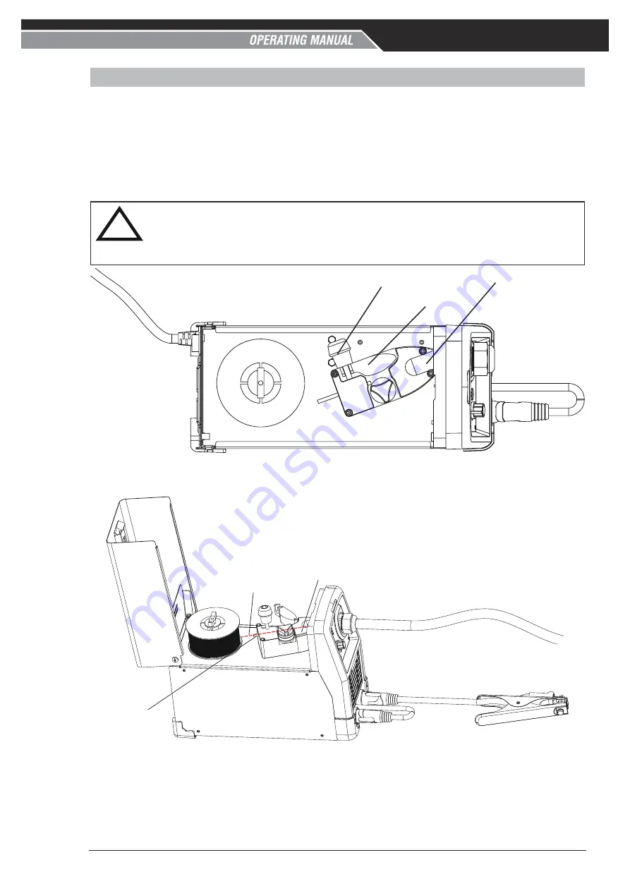
Release the tension from the pressure roller by turning the adjustable wire drive tension screw in an anti-
clockwise direction. Then to release the pressure roller arm, lift the pressure roller arm tension screw upward 
to release the pressure roller arm (Figure 5-5). With the MIG welding wire feeding from the side of the spool 
(Figure 5-6) pass the wire through the inlet guide, between the rollers, through the outlet guide and into the 
MIG Gun. Re-secure the pressure roller arm and wire drive tension screw and adjust the pressure accordingly 
(Figure 5-5). Remove the contact tip from the MIG Gun. With the MIG Gun lead reasonably straight, feed the 
wire through the Gun by depressing the trigger switch. Fit the appropriate contact tip. 

!!


WARNING

Keep hands clear of the contact tip holder while feeding wire through to the gun. The wire can easily pierce you skin 
resulting in injury.
Keep MIG Gun away from eyes and face.

Art # A-14854

Wire Drive Tension Screw

Pressure Roller Arm

Outlet Guide

Figure 5-5: Wire Drive Assembly Components

Art # A-14855

MIG Welding Wire

Inlet Guide

Outlet Guide

Figure 5-6: MIG Welding Wire - Installation

Summary of Contents for CIGWELD EasyWeld 130

Page 1: ...1 10 2021 Manual No 0 5618 Art A 14846 EasyWeld 130 W1201130 HandyWeld 130 W1200130 OUTPUT CURRENT STICK WARRANTY 2 WARRANTY 1 MIG EasyWeld HandyWeld 130 OPERATING MANUAL DIGITAL PRE SETS MIG QUICK SE...

Page 2: ...r constant effort to bring you the best products we may make an improvement that does not get reflected in the manual If you are ever in doubt about what you see or read in this manual with the produc...

Page 3: ...LD Pty Ltd All rights reserved Reproduction of this work in whole or in part without written permission of the publisher is prohibited The publisher does not assume and hereby disclaims any liability...

Page 4: ...erform in conformity with the description thereof contained in this manual and accompanying labels and or inserts when installed operated maintained and repaired in accordance with the instructions pr...

Page 5: ...following has been used in the design AS 1674 2 2007 Safety in welding and allied processes Part 2 Electrical AS 60974 1 2020 Arc Welding Equipment Part 1 Welding Power Sources AS NZS 3760 2010 In se...

Page 6: ...upply Voltage Requirements 3 1 3 05 Generators 3 1 3 06 Extension Leads 3 1 3 07 Electromagnetic Compatibility 3 2 SECTION 4 OPERATION 4 1 4 01 Overview 4 1 4 02 Power Source Controls Indicators and F...

Page 7: ...Power Source 6 1 6 03 Cleaning the Feed Rolls 6 1 6 04 Basic Troubleshooting 6 1 6 05 Welding Power Source Problems 6 2 SECTION 7 KEY SPARE PARTS 7 1 7 01 Key Spare Parts 7 1 7 02 MIG Gun 3m CMG13DL P...

Page 8: ...This Page Intentionally Blank...

Page 9: ...ctrical earth ground 11 Do not touch electrode while in contact with the work ground circuit 12 Use only well maintained equipment Repair or replace damaged parts at once 13 In confined spaces or damp...

Page 10: ...cess Approximate Range of Welding Current in Amps Minimum Shade Number of Filter s Manual Metal Arc Welding covered electrodes MMAW Less than or equal to 100 8 100 to 200 10 200 to 300 11 300 to 400 1...

Page 11: ...parks can strike flam mable material 3 Remove all flammables within 35 ft 10 7 m of the welding arc If this is not possible tightly cover them with approved covers 4 Be alert that welding sparks and h...

Page 12: ...AboutWelding AndThe Effects of Low Frequency Electric and Magnetic Fields The following is a quotation from the General Conclusions Section of the U S Congress Office of Technology Assessment Biologic...

Page 13: ...y 550 N W LeJeune Rd Miami FL 33126 Safety and Health Standards OSHA 29 CFR 1910 from Superintendent of Documents U S Government Printing Office Washington D C 20402 Recommended Safe Practices for the...

Page 14: ...EasyWeld HandyWeld 130 GENERAL INFORMATION 1 6 0 5618 This Page Intentionally Blank...

Page 15: ...its accessories 2 01 How To Use This Manual This Owners Manual only applies to the Part Numbers listed on page i To ensure safe operation read the entire manual including the chapter on safety instru...

Page 16: ...al Arc Welding GMAW Increase Decrease Circuit Breaker AC Auxiliary Power Remote Duty Cycle Percentage Amperage Voltage Hertz cycles sec Frequency Negative Positive Direct Current DC Protective Earth G...

Page 17: ...ding con sumables and procedures The following instructions detail how to correctly and safely set up the machine and give guidelines on gaining the best efficiency and quality from the power sources...

Page 18: ...a proper skid before transporting 2 09 Duty Cycle The rated duty cycle of a Welding Power Source is a statement of the time it may be operated at its rated welding current output without exceeding the...

Page 19: ...Voltage MIG Weld Mode 78V Effective Input Current I1eff refer Note 2 9 4A at 240V input voltage 10A at 230V input voltage Maximum Input Current I1max 21A at 240V input voltage 22A at 230V input voltag...

Page 20: ...on their outputs These circuit breakers usually will have a small reset button and will trip much faster than a switchboard type circuit breaker This may result in not being able to achieve full outp...

Page 21: ...l 0 8 0 9mm V Groove hard wires W4012907 Feed Roll 0 8 0 9mm V Groove Knurled flux cored supplied and fitted on the machine W4013010 Argon Mini Regulator and Gas Hose Kit includes CutSkill Regulator F...

Page 22: ...lding Helmet Variable Shade 9 13 Tribal 454324 WeldSkill Auto Darkening Welding Helmet Variable Shade 9 13 Oz Flag 454335 WeldSkill Auto Darkening Welding Helmet Variable Shade 9 13 Flaming Skull 4543...

Page 23: ...xtension leads may impact welding performance and operation 3 01 Environment These units are designed for use in environments with increased hazard of electric shock A Examples of environments with in...

Page 24: ...al equipment e g guarding of industrial equipment 5 The health of people around e g the use of pacemakers and hearing aids 6 Equipment used for calibration and measure ment 7 The time of day that weld...

Page 25: ...e g ship s hull or building steelwork a connection bonding the workpiece to earth may reduce emissions in some but not all instances Care should be taken to prevent the earthing of the work piece inc...

Page 26: ...EasyWeld HandyWeld 130 INSTALLATION 3 4 0 5618 This Page Intentionally Blank...

Page 27: ...wire welding current at given settings could vary accordingly to the type of MIG wire in use The operator should use the plate thickness pre set welding current values as a guide then finally adjust...

Page 28: ...Speed WFS and Volts Trim Once the desired parameter is selected by pressing the Control Knob the setting can be adjusted by turning the Control Knob Clockwise to increase value or by turning the Contr...

Page 29: ...d actual welding values due to factors including the mode of welding differences in consumables gas mixtures individual welding techniques and the transfer mode of the welding arc ie dip versus spray...

Page 30: ...ose Kit W4013010 is required in order to use Gas Shielded Solid MIG Welding Wires The Gas Inlet connection is a barb type inlet fitting located on the rear of the machine which is used to supply the a...

Page 31: ...the plastic buckle Step 2 Whilst holding the back of the plastic buckle position the buckle so the nylon strap falls away from the front slotted hole on the buckle This will then allow you to feed th...

Page 32: ...EasyWeld HandyWeld 130 OPERATION 4 6 0 5618 This Page Intentionally Blank...

Page 33: ...er 180Amps and a minimum of 18 LPM for welding amperages over 200Amps A lower gas flow will affect the welding quality and cause a porous weld while high gas flow results in bigger consumption of gas...

Page 34: ...der Installation 1 Remove cylinder valve plastic dust seal Clean the cylinder valve outlet of impurities that may clog orifices and damage seats before connecting the regulator flowmeter Crack the val...

Page 35: ...ow rate NOTE 5 It may be necessary to re check the shielding gas regulator flowmeter flow rate following the first weld sequence due to back pressure present within shielding gas hose assembly 2 To re...

Page 36: ...pool 100mm diameter assemble parts in the sequence shown below in Figure 5 4 The nut and spring tighten the brake The brake is correctly adjusted when the spool stops within 10 to 20mm measured at the...

Page 37: ...outlet guide and into the MIG Gun Re secure the pressure roller arm and wire drive tension screw and adjust the pressure accordingly Figure 5 5 Remove the contact tip from the MIG Gun With the MIG Gu...

Page 38: ...tighten the pressure tension adjustment screw if it slips WOOD Tighten Feed wire to check drive roll pressure Tighten knob enough to prevent slipping Art A 14868 Figure 5 7 WARNING Keep hands clear o...

Page 39: ...hanging the Feed Roll 5 06 Wire Reel Brake When fitting the Wire Spool the adjustment of the nut will control the MIG Wire Spool Brake Clockwise rotation of this nut tightens the brake The Brake is co...

Page 40: ...5 02 E Switch the Power Source On Off switch located on the rear of the Power Source to the On position and ensure the Power indicator on the Front Panel is illuminated F Select MIG Gasless Mode usin...

Page 41: ...elect MIG Gasless Mode Figure 5 13 Select Welding Wire Diameter NOTE Quick Set wire sizes for MIG GASLESS Flux Cored Wire are 0 8mm and 0 9mm diameter Figure 5 14 Select Plate Material Thickness At th...

Page 42: ...selected by first selecting Volts function and then holding the Control Knob depressed for approximately 3 seconds The display will change from the Pre set Volts Value to display the Volts Trim Value...

Page 43: ...cess Selection Control button Refer to section 4 02 1 Page 4 1 G Feed wire through the wire drive mechanism Refer to section 5 03 WARNING Moving Parts can cause injury H Connect the work lead to the n...

Page 44: ...on Control button refer to section 4 02 1 for further information Figure 5 19 Select MIG Gas Mode Figure 5 20 Select Welding Wire Diameter NOTE Quick Set wire sizes for MIG GAS SolidWire are 0 6mm and...

Page 45: ...elected by first selecting Volts function and then holding the Control Knob depressed for approximately 3 seconds The display will change from the Pre set Volts Value to display the Volts Trim Value T...

Page 46: ...n be used to weld thin and fairly thick steels and some non ferrous metals in all positions Art A 8991_AB Shielding Gas Molten Weld Metal Solidified Weld Metal Nozzle Electrode Arc Base Metal GMAW Pro...

Page 47: ...ry poor weld The electrode wire is not energized until the gun trigger switch is depressed The wire may therefore be placed on the seam or joint prior to lowering the helmet Butt Horizontal Welds Dire...

Page 48: ...ition rate and the mechanical properties These variables are Type of electrode wire Size of electrode wire Type of gas not applicable to self shielding wires FCAW Gas flow rate not applicable to self...

Page 49: ...Nozzle Axes Art A 08998_AB Longitudinal Angle Axis of Weld Transverse Angle Figure 5 33 Art A 08999_AC Nozzle Angle Right Handed Operator Direction of Gun Travel Leading or Pushing Angle Forward Point...

Page 50: ...re required A thinner electrode wire needs more Wire Feed Speed to achieve the same current level A satisfactory weld cannot be obtained if the Wire Feed Speed and Voltage settings are not adjusted to...

Page 51: ...ications only It is excellent for single pass lap llet and butt welding of thin gauged galvanised and mild steels 0 9mm Minispool 0 9kg WG0909 AUTOCRAFT 316LSI SOLID STAINLESS STEEL MIG WIRE 0 8mm Min...

Page 52: ...inder is not empty and the flow meter is correctly adjusted to 15 litres per minute 2 Gas leaks Check for gas leaks between the regulator cylinder connection and in the gas hose to the Power Source 3...

Page 53: ...eased amounts of swarf are produced by the wire passing through the feed roll when excessive pressure is applied to the pressure roller adjuster B Swarf can also be produced by the wire passing throug...

Page 54: ...ng B Replace contact tip C Incorrect shielding gas C Check shielding gas D Insufficient or excessive heat input D Adjust the Wire Feed Speed control or the voltage control 6 Weld cracking A Weld beads...

Page 55: ...ls present inside this product Do not attempt to open or repair unless you are a qualified electrical tradesperson Disconnect the Welding Power Source from the Mains Supply Voltage before disassemblin...

Page 56: ...work piece C The Pre set voltage is too high C Decrease the Pre set voltage D The MIG Welding Wire in use is not consistent with the selected MIG wire diameter e g 0 8mm wire is selected but 0 9mm wi...

Page 57: ...MIG Gun polarity lead is not connected into a welding output terminal A Connect the MIG Gun polarity lead to either the positive welding output terminal or the negative welding output terminal as requ...

Page 58: ...gas line Have an accredited CIGWELD service provider repair or replace gas valve Table 6 1 Error Code CAUSE REMEDY 1 E05 A MIG Gun Trigger held depressed whilst turning Power Source ON A Ensure that...

Page 59: ...HANDYWELD 130 POWER SOURCE KEY SPARE PARTS ITEM PART NUMBER DESCRIPTION 1 W7007240 Control Knob 2 W7007241 PCBA Display 3 W7007242 Wire Drive Assembly 4 W7007243 Spool Hub Assembly 5 W7007244 Fan Asse...

Page 60: ...ER DESCRIPTION 1 W6000600 Gas Nozzle 2 OTW11 23 R Contact Tip 0 6mm Pack of 10 OTW11 30 R Contact Tip 0 8mm Pack of 10 OTW11 35 R Contact Tip 0 9mm Pack of 10 OTW11 40 R Contact Tip 1 0mm Pack of 10 3...

Page 61: ...IN BOARD IF LG1 LE HE HG1 C7 C8 D3 D4 D10 C13 C12 D5 D7 Q1A Q1B Q2A Q2B HG2 LG2 5 R7 C11 5 6 4 1 T4 1 3 4 2 BR1 C9 3 4 K1B t RT1 R01 R02 C4 R12 R13 D1 D2 4 1 3 2 T1 FLQ1 FLQ2 FLQ1 C3 R0_2 v RY1 L2 AC2...

Page 62: ...EasyWeld HandyWeld 130 APPENDIX A 2 0 5618 This Page Intentionally Blank...

Page 63: ...S WARRANTY ARE VOID IF REPLACEMENT PARTS OR ACCESSORIES ARE USED WHICH IN CIGWELD S SOLE JUDGEMENT MAY IMPAIR THE SAFETY OR PERFORMANCE OF ANY CIGWELD PRODUCT PURCHASER S RIGHTS UNDER THIS WARRANTY AR...

Page 64: ...No employee agent or representative of CIGWELD is authorized to change this warranty in any way or grant any other warranty and CIGWELD shall not be bound by any such attempt Correction of non conform...

Page 65: ...EasyWeld HandyWeld 130 This Page Intentionally Blank...

Page 66: ...International Enquiries Tel 61 3 9474 7508 Fax 61 3 9474 7488 cigweld com au Malaysia No 14 Jalan Teknologi 3 1 Selangor Science Park 1 Kota Damansara 47810 Petaling Jaya Malaysia Tel 60 3 6145 0995...

Reviews: