


BATTERY PACKS
The battery pack connects to the bottom of the unit and
delivers a nominal 7.5 Volts dc to the radio. A recessed
on/off switch for the radio is located on the battery pack. An
internal fuse located in the radio’s Battery Plate protects the
radio and battery from excessive current draw. The battery
packs are available in several different capacities and sizes.
Radio contacts located on the top of the pack include
switched power, ground, the speaker enabling contacts and a
continuous power contact. In addition, four contacts are lo-
cated on the rear of the battery pack. These four contacts
provide connections to the slip-in type chargers or vehicular
chargers/repeaters while the battery pack is still connected
to the unit. The battery charging contacts are diode pro-
tected from external shorts.
The chargers utilize an internal thermistor in the battery
pack to sense temperature and automatically control charge
rate of the battery. This allows for a maximum charge rate
without overheating the battery pack. All battery packs can
be charged in less than 11/2 hours with the rapid type charg-
ers. Nominal full charge time in a standard charger is 14
hours. The Service Section contains a detailed outline and
schematic diagram of a typical battery pack. Further service
information for the battery packs is also presented in the
Service Section.
Chargers are available with nominal charge times of one
hour (rapid) and fourteen hours (standard). Combinations
include single (1) and multi (5 or 6) position, standard and
rapid charge units. In addition, the vehicular chargers/re-
peaters simultaneously charge the battery while the radio is
operating.
The battery packs should be fully charged in an appro-
priate charger before they are placed into service. This ap-
plies to new battery packs received from the factory and to
battery packs that have been stored for long periods of time.
A fully charged battery pack should have an open-terminal
voltage greater than 7.5 Volts. A battery pack in need of a
charge will cause the low battery "BAT" status flag on the
radio to turn on. This flag will turn on when the battery
pack’s voltage drops below approximately 6.8 Volts. The
low battery alert tone will also be heard when the battery
pack needs charging.
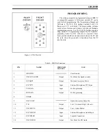
UNIVERSAL DEVICE CONNECTOR
The UDC is located on the side of radio just above the
PTT and Monitor Buttons. Various equipment such as the
audio accessories can be connected to the radio via the
UDC. The programming equipment is also connected to it
when the personality is programmed into the radio. The
UDC furnishes an excellent first-check-point for initial
bench checks without the need to disassemble the radio. Ta-
ble 2 lists all pins and their appropriate function. When the
radio is turned on it senses the resistance value between
UDC pins 9 and 1 and switches the appropriate circuits to
provide proper radio-to-accessory operation.
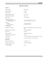
USABLE FREQ.
RANGE (MHz)
OPTION
NUMBER
PART NUMBER
TYPE
COLOR
BANDS
470 - 512
PANC1G
19B234804P13
Helical
Orange
440-514
PANC1N
19A149061P12
Whip
Orange
Table 1 - UHF Antennas
LBI-33056
10