GUIDE TO ASSEMBLY OF ERICA SYNTHS DIY MODULATOR
If you are reading this, most probably, you are about to build Erica
Synths DIY Modulator. This module is 35mm deep, skiff friendly,
has solid mechanical construction and doesn’t require wiring.
The Modulator essentially is LFO with simultaneous triangle and
square wave outputs, clockable S&H with external CV input and
noise source. A kit comes with two versions of noise generator –
simple, transistor-based and more complex Zener diode-based one.
Latest provides perfect, full spectrum white noise.
The DIY Envelope kit comes in three versions:
1) 3 PCBs + S&H chip + connectors,
2) 3 PCBs+ S&H chip + conn panel,
3) Full kit.
FEATURES:
LFO with triangle and pulse wave outputs
Choice of transistor-based or Zener diode-based noise generator
for massive, full spectrum white noise
S&H circuit based on rare, high quality S&H chip
S&H CV and clock inputs
SPECIFICATIONS:
•
LFO output amplitude
-5V…+5V
•
LFO frequency range
0,1…20Hz (configurable)
•
Noise output level
10Vptp
•
S&H CV input level
up to 20Vptp
•
Panel width
8HP
•
Module depth
35mm
•
Power consumption
27mA@+12V, 22mA@-12V
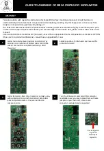
1
3
4
2
5
1
2
3
4
5
Set desired LFO frequency! LED gives visual
feedback on LFO pulse wave output.
This is white noise output
This is S&H circuit input. Apply here and turn
them into stepped CVs on the S&H output. If
no external clock is applied, S&H frequency is
defined by FREQUENCY knob setting.
This is external S&H clock input. If nothing is
patched here, it’s normaled to the LFO.
These are LFO and S&H outputs.


