


EG_GenLoc54e_1040_UG_002_UK
Page 71 / 86
Descriptions and non-contractual illustrations in this document are given as an indication only.
ERCOGENER reserves the right to make any modifications.
Dct_427_02
8.2.4
Inputs/Output
By default, the GenLoc 54e provides:
3 opto-coupled inputs (E1, E2 and E4)
2 opto-coupled inputs insulated (E3 and E5)
3 open collector outputs (S1 up to S3).
2 analog inputs (ANA1, ANA2).
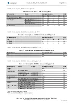
8.2.4.1
Opto-coupled inputs
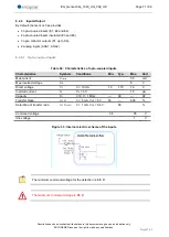
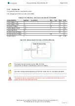
Table 56 : Characteristics of opto-coupled inputs
Characteristics
Symbols
Conditions
Min.
Typ.
Max.
Unit
Max.current
I
F (rms)
50
mA
Max.inverted voltage
V
R
5
V
Direct voltage
V
F
I
F
= 10 mA
1.0
1.15
1.3
V
Inverted current
I
R
V
R
= 5 V
10
µA
Capacity
C
T
V=0, f = 1 MHz
---
30
---
pF
Transfer Ratio
I
C
/ I
F
I
F
= 5 mA, V
CE
= 5 V
50
---
600
%
Saturation of transfer ratio
I
C
/ I
F (SAT)
I
F
= 1 mA, V
CE
= 0.4 V
60
%
Command voltage
3,5
35
V
Idle voltage
1
V
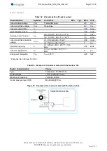
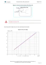
Figure 33 : Internal electric scheme of the inputs
The minimum command voltage for the detection is:
3.5 V
The maximum command voltage is:
35 V


