EPSON Stylus Pro 7400/7800/9400/9800
Revision B
Operating Principles
Print Mechanism Components
153
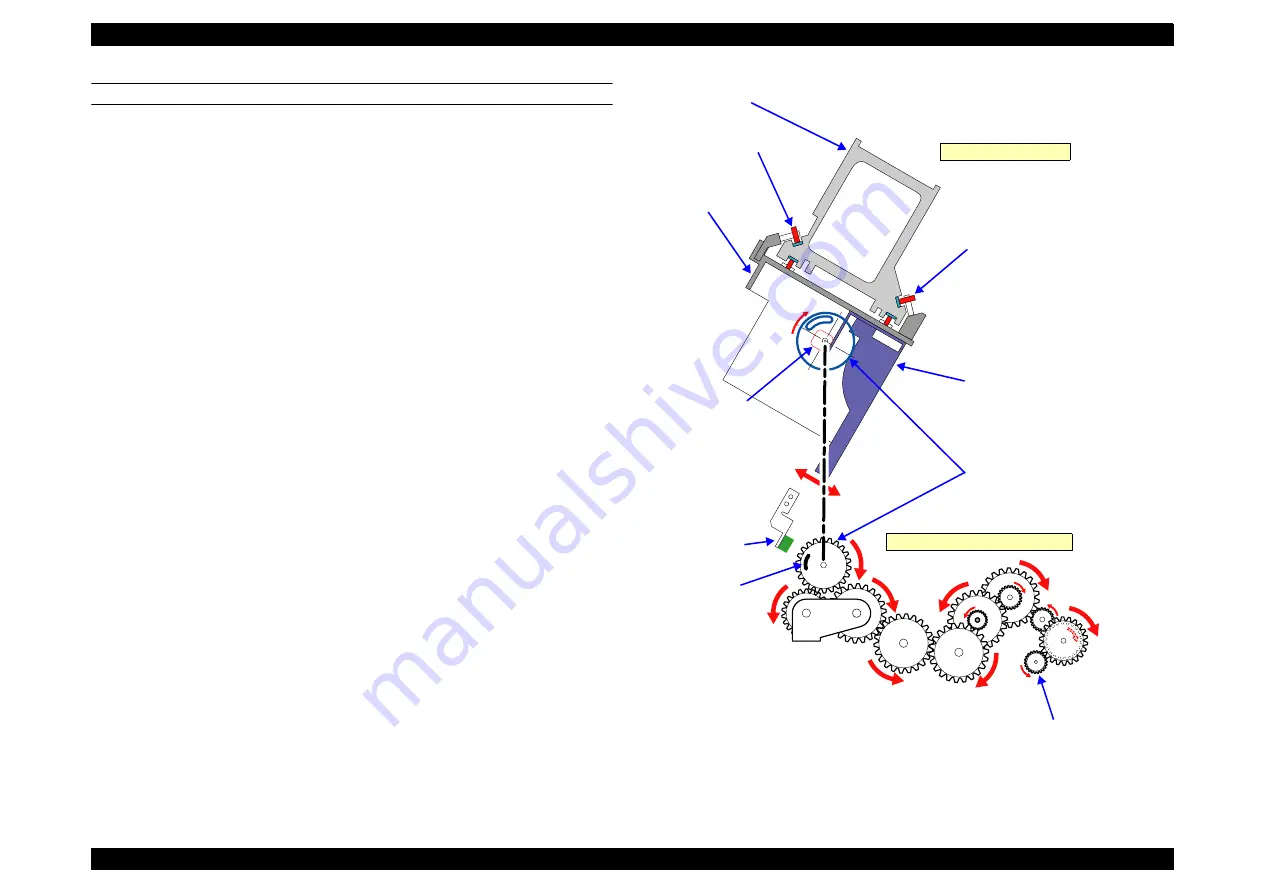
PLATEN GAP ADJUSTMENT UNIT
In order to maintain the print precision, it is necessary to maintain the carriage (= head)
mounting position so that it is always a constant distance from the surface of the paper.
In this printer, the print head nozzle surfaces and platen surface are variable
mechanisms so that the gap between the paper printing surface and the head nozzle
surface can be kept constant.
The carriage has a 2-body construction with a sub-carriage on which the print heads are
mounted attached to the carriage which forms the base. The sub-carriage moves in the
vertical direction with respect to the paper surface. This movable system uses a cam (=
PG). When the sub-carriage is in the HP position (= right end), the pump motor and the
gear mounted on the cam shaft engage, the motor’s rotation (reverse) drives the cam
and the sub-carriage is positioned at the proper gap position.
In order to maintain the distance between the print head nozzle surface and the paper
properly, the thicknesses of the paper used are classified into 5 levels for PG setting,
namely, minimum PG (0.8 mm), small PG (1.2 mm), medium PG (1.6mm), large PG
(2.1 mm), and maximum PG (2.6 mm).
The sensors used in the platen gap adjustment unit are explained below.
Figure 2-3. Carriage Mechanical Unit and PG Adjustment Unit
Slide Gear
Sub-carriage (Head Mounted)
Bearing (Roll Type)
CR Guide Rail
Carriage
PG (Head SLID)
Right Side of Carriage
Bearing (Roll Type)
PG HP Sensor
HP Detection
Flag
Pump Motor Drive Force
(CCW)
Right Side of Printer Mechanism
Summary of Contents for Stylus Pro 7400
Page 1: ...EPSONStylusPro7400 7800 9400 9800 Large Format Color Inkjet Printer SERVICE MANUAL SEIJ05002 ...
Page 10: ...C H A P T E R 1 PRODUCTDESCRIPTION ...
Page 147: ...C H A P T E R 2 OPERATINGPRINCIPLES ...
Page 170: ...C H A P T E R 3 TROUBLESHOOTING ...
Page 207: ...C H A P T E R 4 DISASSEMBLY ASSEMBLY ...
Page 292: ...C H A P T E R 5 ADJUSTMENT ...
Page 373: ...C H A P T E R 6 MAINTENANCE ...
Page 380: ...C H A P T E R 7 APPENDIX ...
Page 385: ...Model PX 7500 7500S 9500 9500S Board C594 Main Sheet 1 of 4 Revison G ...
Page 386: ...Model PX 7500 7500S 9500 9500S Board C594 Main Sheet 2 of 4 Revison F ...
Page 387: ...Model PX 7500 7500S 9500 9500S Board C594 Main Sheet 3 of 4 Revison F ...
Page 388: ...Model PX 7500 7500S 9500 9500S Board C594 Main Sheet 4 of 4 Revison E ...
Page 389: ...Model PX 7500 7500S 9500 9500S Board C594 SUB Sheet 1 Revison C ...
Page 390: ...Model PX 7500 7500S 9500 9500S Board C594 SUB B Sheet 1 Revison E ...
Page 391: ...Model PX 7500 7500S 9500 9500S Board C594 SUB C Sheet 1 Revison D ...
Page 392: ...Model PX 7500 7500S 9500 9500S Board C594 PNL Sheet 1 Revison D ...
Page 396: ...PX 7500 7500S E PS ON S TYLUS PR O 7400 7800 No 03 R ev 01 C594 E LE C 011 202 201 200 ...
Page 397: ...PX 7500 7500S E PS ON S TYLUS PR O 7400 7800 No 04 R ev 01 C594 E LE C 021 203 204 ...
Page 398: ...PX 7500 7500S E PS ON S TYLUS PR O 7400 7800 No 05 R ev 01 C594 POWE 011 300 301 302 ...
Page 403: ...PX 7500 7500S E PS ON S TYLUS PR O 7400 7800 No 10 R ev 01 C594 ME CH 051 700 701 X15 700 ...
Page 410: ...R ev 01 C595 E LE C 011 200 201 202 PX 9500 9500S E PS ON S TYLUS PR O 9400 9800 No 03 ...
Page 411: ...PX 9500 9500S E PS ON S TYLUS PR O 9400 9800 No 04 R ev 01 C595 E LE C 021 204 203 ...
Page 412: ...PX 9500 9500S E PS ON S TYLUS PR O 9400 9800 No 05 R ev 01 C595 POWE 011 300 302 301 ...
Page 417: ...PX 9500 9500S E PS ON S TYLUS PR O 9400 9800 No 10 R ev 01 C594 ME CH 051 701 X15 700 700 ...


