background image

EPSON Stylus PHOTO RX640/650

Revision C

Maintenance

Overview

81


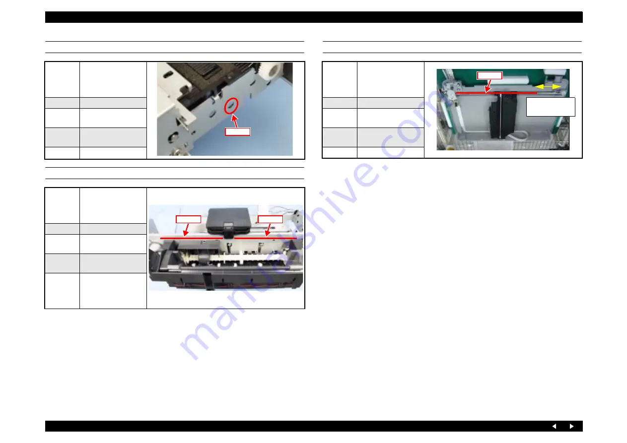
LUBRICATION AT INSTALLATION OF I/S ASSY

LUBRICATION OF PRINTER MECHANISM ASSY

LUBRICATION OF SCANNER

Lubrication 
Points

Printer frame: 
Surface which comes in 
contact with the Clutch 
Gear

Type

G-71

Amount of 
Application

One round

Applying 
tool

Injector

Precautions

Lubrication 
Points

Surfaces which come in 
contact with the 
carriage (rear of printer 
frame)

Type

G-71

Amount of 
Application

ø 1x15 cm (x2)

Applying 
tool

Injector

Precautions

Move the Carriage 
Assy to the center and 
apply grease to the right 
and left areas.

G-71

G-71

G-71

Lubrication 
Points

Surface of scanner CR 
shaft Revision 
Cwithout 5cm area 
from right end

Type

G-71

Amount of 
Application

Lubricate thinly

Applying 
tool

Paint brush

Precautions


G-71

Do not lubricate 
in 5cm area

Summary of Contents for Stylus Photo RX640 series

Page 1: ...EPSON StylusPHOTORX640 650 Scanner Printer Copier SERVICE MANUAL SEMF05003 ...

Page 2: ...nformed of them The contents of this manual are subject to change without notice The above not withstanding SEIKO EPSON CORPORATION can assume no responsibility for any errors in this manual or the consequences thereof EPSON is a registered trademark of SEIKO EPSON CORPORATION General Notice Other product names used herein are for identification purpose only and may be trademarks or registered tra...

Page 3: ...TRONIC COMPONENTS 4 WHEN DISASSEMBLING OR ASSEMBLING A PRODUCT MAKE SURE TO WEAR GLOVES TO AVOID INJURIES FROM METAL PARTS WITH SHARP EDGES 5 WHEN USING COMPRESSED AIR PRODUCTS SUCH AS AIR DUSTER FOR CLEANING DURING REPAIR AND MAINTENANCE THE USE OF SUCH PRODUCTS CONTAINING FLAMMABLE GAS IS PROHIBITED WARNING 1 REPAIRS ON EPSON PRODUCT SHOULD BE PERFORMED ONLY BY AN EPSON CERTIFIED REPAIR TECHNICI...

Page 4: ...uct APPENDIX Provides the following additional information for reference Connection with Connectors Circuit Boards Component Layout Exploded diagram Parts List Symbols Used in this Manual Various symbols are used throughout this manual either to provide additional information on a specific topic or to warn of possible danger present during a procedure or an action Be aware of all symbols when they...

Page 5: ...e of Issue Description A December 19 2005 First Release B March 8 2006 Error correction Checkpoint Scanner Home Position Adjustment on page 75 C April 17 2006 Addition of scanner lubrication point Lubrication of SCANNER on page 81 ...

Page 6: ...8 2 2 1 Overview 18 2 2 2 Features 18 2 2 3 Circuit Board Constitution 18 Chapter 3 Troubleshooting 3 1 Overview 20 3 1 1 Specified Tools 20 3 1 2 Preliminary Checks 20 3 1 3 Procedure for Troubleshooting 20 3 2 Troubleshooting When There is Error Display 21 3 2 1 Error List 21 3 2 2 Warning List 23 3 2 3 FATAL Error 28 3 3 Troubleshooting When There is No Error Display 31 3 3 1 Troubleshooting fo...

Page 7: ... Scale 61 4 5 2 I S Assy 62 4 5 3 ASF Assy 63 4 5 4 APG Assy 64 4 5 5 CR Motor 65 4 5 6 Carriage Assy 66 4 5 7 Eject Frame Assy 68 4 5 8 Upper Paper Guides 69 4 5 9 Paper Guide Front Assy 70 Chapter 5 Adjustment 5 1 Overview 72 5 1 1 Adjustment by Use of Adjustment Program TBD 72 5 1 2 PG Adjustment 73 5 1 3 Scanner Home Position Adjustment 75 5 1 4 Preparations for Use of the Adjustment Program 7...

Page 8: ...C H A P T E R 1 PRODUCTDESCRIPTION ...

Page 9: ...led to support printing on Iron On Cool Peel Transfer Paper Photo Stickers printing to enable printing on photo stickers in photo quality Memory card print functions The printer equipped with a memory card reader function has a standalone memory card printing functions In addition the following features are also available Index Sheet printing supported whereby images can be selected simply by mark...

Page 10: ...CR interval Programmable in 0 0176 mm 1 1440 inch steps Platen print prevention Printing using a Borderless layout Top detection and PW detection implemented for platen print prevention Printing using a layout with borders platen print prevention with the paper width of 1st page or 1st job Economy printing mode no platen print prevention Table 1 3 Basic Specifications Items Specifications Product ...

Page 11: ...receiver sensitivity of communication Devices and antenna performance C H E C K P O I N T Detailed information on above mentioned external storage devices Bluetooth adapter and devices compatible with IrDA infrared data association is available on EPSON web site Table 1 4 Main specifications Items Specifications Standards Universal Serial Bus Specifications Revision 2 0 Printer Universal Serial Bu...

Page 12: ... becomes valid if a medium is inserted there It is not necessary to reinsert the medium before it is accessed If media are not inserted in any of the slots the valid slot is changed to the slot of the highest priority Compact Flash This is not affected by the order of media insertion in or removal from unselected slots Items Specifications Standards Compliant with the infrared data communication s...

Page 13: ...n Magenta Yellow Light Cyan Light Magenta Storage temperature 20 C to 40 C Installed Within 1 month at 40 C An acceptable change in temperature is 45 C or less within this range 30 C to 40 C Packing storage Within 1 month at 40 C Dimensions 12 7 mm W x 73 46 mm D x 55 25 mm H Weight 39 g C H E C K P O I N T Ink cartridges whose validity has expired should not be used The ink in cartridges freezes ...

Page 14: ...tance Temperature 10 35 C operation mode 3 20 60 C non operation mode 1 1 month when at 40 C 120 hour when at 60 C Humidity 20 80 RH operation mode 2 3 5 85 RH non operation mode 1 2 Impact 1 G 1 x 10 3 seconds operating 2 G 2 x 10 3 seconds not operating 1 Vibration 0 15G 10 55Hz operating 0 50G 10 55Hz not operating 1 Table 1 5 Lifetime Total print volume 16 000 pages A4 Letter or 5 years the sh...

Page 15: ...C H A P T E R 2 OPERATINGPRINCIPLES ...

Page 16: ... the PF Motor to load paper into the Printer Mechanism Eject Assy Driven by the PF Motor to eject the paper CD R Tray As the Stacker is moved up and down by manual operation the paper eject frame moves up and down so that its height can be adjusted to the media I S Assy Located in the right end of the mechanism performs capping the Printhead while it is not used and sucking waste ink The waste ink...

Page 17: ...Resolution 1440 pulse inch PTS detector PF Type Linear encoder Resolution 180 pulses inch PW detector Function Paper left and right edge before and during printing Paper top edge before printing Paper bottom edge during printing CD R top bottom right and left edges before printing Detection method Reflective photosensor APG detector Function APG position detection Detection method Transmissive typ...

Page 18: ...ployment of UBEC Ultra Block Encode Equipped with a color LCD 2 5 inch low temperature poly silicon TFT liquid crystal as a standard feature Power consumption is suppressed by executing the following actions at transition to the power save mode Lowering the supply voltage for main power Cutting off the photo electric current of the photo sensor Stopping the motor drive circuit Stopping the UDL clo...

Page 19: ...C H A P T E R 3 TROUBLESHOOTING ...

Page 20: ...rupt temperature change The Unit should not be located near waterworks near humidifiers near heaters or near flames in a dusty atmosphere or in a place where the Unit can be exposed to blast from an air conditioner The Unit should not be located in a place where volatile or inflammable gases are produced The Unit should not be located in a place where it can be exposed to direct rays of the sun Th...

Page 21: ...artridges are correctly installed Press OK to continue Guide Display OK Continue Install the normal ink cartridges correctly and press the OK button Message related to Ink 4 Ink end Color icons Ink out Press the OK button to replace the cartridges Guide Display OK Continue Install the normal ink cartridges filled with ink correctly and press the OK button Scanner FATAL Error An error that cannot b...

Page 22: ...FATAL Error p 28 Maintenance Error The printer requires maintenance due to waste liquid overflow or elastomer tube replacement time etc Service required Parts inside your printer are at the end of their service life See your manual for details Guide Display Power Button Turn off Turn off the power Refer to 3 2 3 FATAL Error p 28 CD DVD guide open When startup CD DVD guide open The front tray is in...

Page 23: ...installed The installed ink cartridges listed below differ from the genuine Epson ink cartridges for this printer Y BK LC LM M C The use of other products may affect your print quality and could result in printer damage Do you want to continue using the currently installed ink cartridges Yes No Guide Display Make a Selection OK OK Press the OK button BT File size error The document is too large to...

Page 24: ...manual Guide Display OK Finish Press the OK button Film print Cannot recognize the Film A slide or negative could not be recognized Make sure the film holder is properly positioned and the film is inserted in the holder For details see your manual Guide Display OK Finish Press the OK button Combo print error 1 Euro Photo Greeting card error 1 EAI No recognition mark could be found on the template ...

Page 25: ... printing a different memory card was inserted or an image was added or deleted The contents of the memory card have changed Print a new index sheet and try again Guide Display OK Finish Press the OK button Scan to memory error fail to format Error has occurred in formatting the card A problem occurred while formatting Formatting canceled Guide Display OK Finish Press the OK button Scan to memory ...

Page 26: ...otos found Guide Display OK Finish Press the OK button Backup error no card Backup source does not exist No memory card in slot Backup canceled Guide Display OK Finish Press the OK button Backup error no external connection Backup was about to be started without an external device connected External device is not connected or media is not inserted Backup canceled Guide Display OK Finish Press the ...

Page 27: ... CD label print More than one copy has been selected Only 1 copy can be selected Wait for a certain time approx 3 seconds Paper type change for CD printing You are asked if you really desire to clear the settings If you change the settings you must select your photos and number of prints again Guide Display OK OK Back Cancel Press the OK button or Back button Select the number of copies Plural pie...

Page 28: ...ments Bi D Paper feed length with PF Assy Paper feed length with Eject Assy PW adjustment Checking the following parts and replacing the defective one Checking the head FFC CN6 7 for disconnection or breakage Checking the lead wires of the CR Motor CN3 for disconnection or breakage Checking the CR Encoder FFC CN6 for disconnection or breakage Checking the printer frame for adhesion of dirt or insu...

Page 29: ...control F2H PF PID drive time out judgment error F3H PF BS drive time out judgment error APG motor 70H APG error normal drive error An error occurred in the APG operating sequence Checking the installation of the APG Sensor position of the sensor and connection of the connector CN9 Checking the drive of the APG Assy Installation of the composite gear of the ASF Assy APG Assy Standalone operation o...

Page 30: ...Sensor error 60H PW detection error Hi check error PW detector trouble Checking the PW Sensor p 67 Checking the PW Sensor for adhesion of dirt and dust Checking the connection of the FFC Making the following adjustments PW adjustment Checking the following parts and replace the defective one Head FFC Carriage Assy Main Board p 46 Power Supply Board p 54 61H PW detection error Low check error 62H T...

Page 31: ...ge of the card 3 Repeat the paper feed operation several times to clean the surface of the LD Roller or Retard Roller If these steps do not correct the problem replace both the LD Roller and Retard Roller Pick Up Roller and Idle Roller dirty or worn Check to see if no Micro Pearl or oily substance is adhering to the rollers Wipe the rollers with a cloth dampened with alcohol Operation of paper loa...

Page 32: ...mpensation counter and write the maximum value Faulty operation of Paper Eject Roller Check to see if Paper Eject Roller rotates correctly Properly engage the gears driving the Paper Eject Roller Table 3 3 Diagnostics when carriage action is abnormal Condition Cause Check Point Remedy Abnormal carriage operation during printing Carriage does not move smoothly Check to see if there is an obstacle i...

Page 33: ...rly Check to see if Encoder FFC is connected to CR Encoder Board Connect the Encoder FFC to the CR Encoder Board Check for paper bits and dust adhering to CR Encoder Remove paper bits and dust adhering to the CR Encoder Check for damaged Encoder FFC Replace the Encoder FFC Carriage Assy Check for damaged CR Encoder Replace the Carriage Assy Rotary Scale not operating properly Check to see if the R...

Page 34: ...blem with the Head FFC to Printhead connection replace the Printhead Vertical lines are not in alignment Bi D adjustment is not made Check to see if Bi D adjustment has been done properly Perform Bi D adjustment White lines appear in output data Dirt is adhering to CR Guide Shaft Check for dirt adhering to surface of CR Guide Shaft Clean the surface of the CR Guide Shaft with a soft dry cloth PF R...

Page 35: ...voltage of Power Supply Board Check the output voltage of the Power Supply Board When the output voltage is normal Replace the Main Board with a new one When the output voltage is abnormal Replace the Power Supply Board with a new one Table 3 7 Troubleshooting for Printer Stop During Initialization or Printing Condition Cause Check Point Remedy Ink End error is displayed Ink is out Check to see if...

Page 36: ...logging with ink Check to see if there is ink leakage from the Printhead Install the ink cartridges properly If this does not improve the condition replace ink cartridges and the Printhead Table 3 9 Troubleshooting for Faulty Ink Supply or Faulty Waste Ink Discharge Condition Cause Check Point Remedy Ink is not flowing from Printhead to Cap or from Cap to Ink Tube Pump tube collapsed Visually chec...

Page 37: ...ve main board Check to see if main board is not damaged Replace the main board Table 3 11 Troubleshooting for Memory Card Cause Check Point Remedy Driver has not been installed correctly Check to see if a memory card is recognized in the single Assy mode Temporarily remove the driver and then install it again Data has been destroyed Data on card may be destroyed owing to static electricity Check t...

Page 38: ... after power is turned off once and then turned on again CR unit does not operate Table 3 15 CR unit operates but error is indicated Table 3 16 The fluorescent lamp does not turn on Table 3 17 Picture is not read clearly Picture is not read clearly Table 3 19 Communication error Indication error occurs and when communication with the host is tried again Communication error recurs USB interface err...

Page 39: ...cted Is the connector CN13 on the Main Board or either of the connectors CN1 and 2 on the Inverter Board disconnected Yes Connect the connector Defective or life expired lamp Does the lamp light up when it is replaced Yes Replace the TPU Case Assy Defective Inverter Board Is problem solved when the Inverter Board is replaced Yes Replace the Inverter Board Defective main board Replace the main boar...

Page 40: ...C H A P T E R 4 DISASSEMBLYANDASSEMBLY ...

Page 41: ...locate it at a position other than the home position before starting disassembly by turning the power ON and turning it OFF timely As soon as the repaired product has been returned to the user there may be a case a maintenance call occurs because of the expiration of the life of a service part Avoid such a case if possible as follows Check the maintenance counter for regularly replaced parts befor...

Page 42: ...owchart 4 1 Disassembly Procedure PF Motor p 61 CR Motor p 65 Paper Guide Front Assy p 70 Middle Housing p 48 Scanner Unit p 45 Panel Assy p 43 START Printhead p 51 Disassembly of Panel Assy p 44 Disassembly of Scanner Unit p 57 Linear Scale p 52 Waste Ink Pads p 54 Power Supply Board p 54 Stacker Assy p 55 Waste Ink Tray Assy p 50 Printer Mechanism p 53 PF Scale and PF Encoder p 61 I S Assy p 62 ...

Page 43: ...nel Fig 4 2 4 Remove the screws x2 securing the Panel Assy Fig 4 3 5 Lift the Panel Assy and disconnect the FFCs x2 Figure 4 1 Removing the Middle Cover Assy Figure 4 2 Removing the Decorative Panel Figure 4 3 Removing the Panel Unit Figure 4 4 Notes on Installing the Panel Assy Install the decorative panel taking care not to confuse the front and back of the Light Conduction Tubes Fig 4 4 When in...

Page 44: ... can come off For cleaning blow off the dust with a blower When installing the LCD Module make sure that the inside of the LCD Cover is free from dust and dirt Tighten the screws for the LCD Module in the order specified Fig 4 7 After installing the LCD Module route the harness as shown and make sure that it is free from floating Fig 4 7 Install the Shield Plate under the board to board cable When...

Page 45: ... Color Connected to Remarks CN5 White CR Motor Unit 4 pin With ferrite core CN12 FFC CCD Unit 28 pin With ferrite core CN13 Red TPU Unit 2 pin CN14 Yellow HP Sensor 3 pin Put the FFC into the housing as shown Fig 4 11 Put the clamp portion of the black harness red CN 13 of the TPU Unit into the printer body Fig 4 11 Route the harness as shown and set the ferrite cores in place and then stick the a...

Page 46: ... ë Ç Figure 4 12 Main Board Layout Figure 4 13 Removing the Ferrite Core Holder Figure 4 14 Removing the Main Board Assy Figure 4 15 Removing the Main Board A D J U S T M E N T R E Q U I R E D When the Main Board is to be replaced back up the data in EEPROM before starting disassembly if possible After assembly make the following adjustment 5 1 1 Adjustment by Use of Adjustment Program TBD p 72 He...

Page 47: ...e core CN6 FFC Printhead 28 pin With ferrite core CN7 FFC Printhead 25 pin With ferrite core CN8 FFC PF Encoder 5 pin With ferrite core CN9 Black APG Sensor 3 pin With ferrite core CN10 White PE Sensor 3 pin With ferrite core CN11 White CD R Sensor Guide Tray 4 pin CN15 FFC LCD 8 pin CN16 FFC Panel Board 11 pin With ferrite core CN20 White Power Supply Board 3 pin C H E C K P O I N T The methods f...

Page 48: ...9 7 Remove the screws 3 in the front and 2 in the rear securing the Middle Housing Assy Fig 4 20 8 Remove the Middle Housing Assy taking care not to damage any cables or the Waste Ink Assy éüÇÃÉyÅ ÉWÇ ë Ç Figure 4 18 Removing the Stacker Cover Figure 4 19 Removing the Waste Ink Assy and the Hinge Assy Figure 4 20 Removing the Middle Housing Assy C A U T I O N After removing the Waste Ink Assy take...

Page 49: ...ling the Middle Housing check the following Printhead FFCs x2 are lead out properly Fig 4 23 Ground Plate is located in front of printer frame Fig 4 23 The left and right bottom areas of the Front Housing are engaged with the projections of Bottom Housing Fig 4 24 The screws are tightened in the order specified Fig 4 20 Hooks Rear left Left side Rear right After setting the ferrite cores in place ...

Page 50: ...sy take due care not to stain any surrounding objects with waste ink When connecting the Waste Ink Tube wipe the ink if any off the joint area of the tube With ink left adhering to the joint area the tube cannot be connected firmly and thus may easily come off Route the Waste Ink Tube along the hooks of the Housing Lower Assy and take care that the tube is not flattened with the Waste Ink Tray Fig...

Page 51: ...Cover do not use any pointed tool otherwise the FFC may be damaged C H E C K P O I N T Stylus PHOTO RX640 650 does not have any mechanism that permits the operator to unlock the carriage Therefore turn the power ON and unplug the power cable from the wall outlet timely after seeing the movement of the carriage to locate it at a position other than the home position See Page 67 for how to remove th...

Page 52: ...ends or two points of the top and bottom surfaces with your hands do not touch the reading surface Take care that the reading surface is not soiled or scratched C H E C K P O I N T Stylus PHOTO RX640 650 does not have any mechanism that permits the operator to unlock the carriage Therefore turn the power ON and turn it OFF timely after seeing the movement of the carriage to locate it at a position...

Page 53: ...rclockwise by about 15 degrees In such a case the PF Scale may be damaged Take great care not to damage the PF Scale when handling the removed Printer Mechanism Assy Alternatively remove the PF Scale and PF Encoder p 61 Since the back of the CR Frame is lubricated take care not to stain your hand with grease when holding the Printer Mechanism Assy Do not touch any other parts with a greasy hand Pr...

Page 54: ...rtions until they are all the way seated and make sure that they are free from floating A D J U S T M E N T R E Q U I R E D On the occasion of replacing a part with a new one replace all the specified parts with new ones and clear the counter value after assembly 5 1 1 Adjustment by Use of Adjustment Program TBD p 72 Before installing the P S Cover route the connector harness so that it is lead ou...

Page 55: ... x4 securing the Stacker Assy Fig 4 36 6 Holding the right and left Stacker Guide areas remove the Stacker Assy from the Housing Lower 7 Release the hook and remove the gear from the CD R Shaft Both right and left 8 Remove the CD R Shaft from the Stacker éüÇÃÉyÅ ÉWÇ ë Ç Figure 4 34 Removing the CD R Guide Lever Figure 4 35 Removing the CD R Guide Lever Spring Figure 4 36 Removing the Stacker Assy ...

Page 56: ...s with the Stacker in the down position Fig 4 39 y Projections x2 in the rear under the Stacker Guides y Protrusions at right and left sides inserted in guide groove Tighten the screws in the specified order Fig 4 36 See Fig 4 40 for installation of the CD R Guide Lever Spring C H E C K P O I N T If the Stacker is not horizontal in the right and left direction remove the right gear and install the...

Page 57: ...sembly and assembly on a clean bench is ideal Perform disassembly and assembly with care not to damage the document table glass In addition never forget that a very troublesome cleaning is required if dirt sticks to the inside of the document table When installing the Scanner Housing the CR Shaft may come off To avoid such problem with the Lower Housing placed in the upright position install the S...

Page 58: ...45 4 Remove the screw and washers x3 securing the CR Motor Unit Figure 4 43 Removing the Timing Belt Figure 4 44 Removing the CR Assy Figure 4 45 CR Motor Unit and HP Sensor When replacing the CCD Unit the FFC is to be replaced together In installation stick the FFC on the Lower Housing properly so that it is free from floating Fig 4 44 Install the CR Shaft while fitting its grooved end in the gui...

Page 59: ... toward the front 5 Remove the Film Holder 6 Release the right and left hooks 3x2 and remove the TPU Cover éüÇÃÉyÅ ÉWÇ ë Ç Figure 4 46 Removing the TPU Unit Figure 4 47 Removing the TPU Cover When installing the TPU Cover engage the hooks x4 in the front first and then engage the right and left hooks x3 When installing the Harness Cover insert the Harness Clamp area in the position shown below fir...

Page 60: ...uting the Lead Wires TPU Housing Figure 4 49 Removing the LED Relay Board Figure 4 50 Removing the Inverter Board C A U T I O N Never remove the fluorescent tube otherwise dust can enter and impair the scanning quality When the fluorescent tube must be replaced with a new one replace the TPU Housing and fluorescent tube as a single unit Before installing the Top Cover make sure that the lead wires...

Page 61: ... Figure 4 51 Removing the PF Encoder PF Scale Figure 4 52 Removing the Harness Holder Figure 4 53 Removing the PF Motor C A U T I O N Handle the PF Scale with care not to scratch or stain it Do not touch it with your bare hand Install the PF Motor with its labeled area facing outward Fig 4 53 When installing the PF Encoder confirm that the reading area does not come in contact with the PF Scale A ...

Page 62: ... not to splash ink Lubrication is necessary Refer to the following section and lubricate the specified points Lubrication at Installation of I S Assy p 81 After installing the I S Assy to the printer frame make sure that its position is adjusted as shown in Fig 4 55 Tighten the screws in the specified order Fig 4 54 Catch the Waste Ink Tube in the groove shown in the figure on the bottom of the I ...

Page 63: ...astening the ASF Assy and the tip of the Change Lever from the printer frame 8 Remove the composite gear 10 15 2 and remove the ASF Assy Figure 4 57 Lead Wires on the ASF Assy Figure 4 58 LD Roller Guide Figure 4 59 Removing the screw ASF Assy Figure 4 60 Removing the ASF Assy Lubrication is necessary Refer to the following section and lubricate the specified points Lubrication at Installation of ...

Page 64: ...all the composite gear 10 15 5 2 Pass a pin ø2mm or the like through the locating hole in the Right PG Cam on the CR Guide Shaft and that in the printer frame 3 Pass a pin or the like through the locating hole in the spur gear 28 8 and that in the APG Assy With the pins left inserted in the holes install the APG Assy on the printer frame 4 Make sure that all the hooks are engaged properly and the ...

Page 65: ... Figure 4 64 Removing the CR Motor Lubrication is necessary Refer to the following section and lubricate the specified points Lubrication of Driven Pulley p 80 Install the CR Motor with its printed area facing upward Tighten the screws in the specified order Fig 4 64 Install the Timing Belt with the tooth side facing inside and without torsion A D J U S T M E N T R E Q U I R E D Once the CR Motor ...

Page 66: ...the screw and turn the Parallelism Bush toward the front Fig 4 66 11 At the right side of the printer remove the spring remove the washer and the Right PG Cam Fig 4 67 12 Remove the Carriage Assy together with the CR Guide Shaft from the left side of the printer frame éüÇÃÉyÅ ÉWÇ ë Ç Figure 4 65 Removing the Cable Holder Frame Figure 4 66 Removing the Carriage Assy at left side Figure 4 67 Removin...

Page 67: ...g the Cable Holder Frame ensure that it is positioned correctly in the front and back direction Fig 4 65 Both inside and outside toothed Toothed inside No tooth outside Up With the cam positioned outside PG Left Cam APG Sensor Must not touch the sensing area Rear Carriage guide A D J U S T M E N T R E Q U I R E D When installing the Carriage Assy refer to the following sections and perform the nec...

Page 68: ...ective positions shown below on the Eject Frame After installing the Front Frame move the Right EJ Frame Spring to the spring support Fit the shaft holders left and right on the underside of the Eject Frame onto the Paper Eject Roller Shaft Fig 4 72 After installing the Front Frame confirm the engagement of the projections x2 and then tighten the screws in the specified order Fig 4 71 After instal...

Page 69: ...r Paper Guides C A U T I O N When removing the Upper Paper Guides bring down the actuator of the PE Sensor toward the front to avoid damaging it Do not touch any of the rollers otherwise the print quality may drop C H E C K P O I N T The Upper Paper Guides are connected as a single unit with thin fragile bridges as shown with arrows below However these parts are not to be placed on the shaft holde...

Page 70: ...rame pull the Paper Guide Front Assy frontward and then undo the engagement at the right side and remove it Fig 4 78 Figure 4 76 Removing the Paper Guide Front Assy 1 Figure 4 77 Removing the PF EJ Ground Spring Figure 4 78 Removing the Paper Guide Front Assy 2 C A U T I O N Do not touch any of the rubber rollers of the Paper Eject Roller Assy or coated surface of the PF Roller Assy otherwise the ...

Page 71: ...C H A P T E R 5 ADJUSTMENT ...

Page 72: ...djustment tools p 73 Adjustments by use of printer adjustment program Once relevant components have been reassembled or replaced After the assembly of the printer make the adjustments required depending on the removed replaced components p 72 Scanner home position adjustment Once the CR Shaft or Carriage has been removed After the assembly of the Scanner Unit adjust the home position using the ded...

Page 73: ... etc Cleaning CR measurement VH detection CR home position seek PGtype Mechanical default 1 7 Plain paper EPSON special thin paper SF etc Rubbing with PG1 2 is avoided PG 2 35 Envelopes Rubbing with PG1 2 and 1 7 is avoided PG 4 2 CD R printing At ink replacement C A U T I O N The thickness gauge to be used must be free from dust and dirt and from deformation Be sure to clean it before use Take ca...

Page 74: ...e the carriage to a position where the Printhead does not come in contact with gauge 9 Move the carriage to the middle area of the platen and place 1 3 mm thickness gauges at the left and right ends of the platen 10 Pull the Timing Belt to move the carriage to the left end 11 If the carriage does not come in contact with the gauge make the adjustment again 12 Pull the Timing Belt to move the carri...

Page 75: ...uction CXXXXXX Execute FT exe in the folder that has been installed as described above Figure 5 4 Installing the Adjustment Program Scanner Home Position C H E C K P O I N T The EEPROM stores the data of scanner home position adjustment If you can not download the all EEPROM data you should also perform this adsjutment Table 5 3 Tools Tool Name Availability Tool Code PC OS Windows XP Scanner origi...

Page 76: ...appears Confirm that TEST OK is displayed on the top line If TEST OK is not displayed make the adjustment again Figure 5 5 Parameter Setting Figure 5 6 Single Test Dialog Display Figure 5 7 Execution of Home Position Adjustment Figure 5 8 OK Screen C H E C K P O I N T Place the home position adjustment tool in close contact with the upper left corner of the document table Leave the top cover of th...

Page 77: ...C H A P T E R 6 MAINTENANCE ...

Page 78: ...ter is close to its upper limit notify the user and recommend that the waste ink pads are to be replaced If the waste ink pads are not replaced at that time there is a possibility that Maintenance Error can occur just after the printer is returned to the customer After replacement reset the overflow counter protection counter by the adjustment program Table 6 2 Waste Ink Absorption Capacity Waste ...

Page 79: ...cified Take care that no grease adheres to any paper transport parts such as rollers or the Printhead otherwise the print quality may drop Table 6 5 Specified Lubricant etc Type Name Parts Code Available Grease G 71 1304682 EPSON Insulating Tape Acetate Tape 1003963 Lubrication Points PF Roller Shaft and the shaft holders 2 positions right and left Type G 71 Amount of Application ø 1x3 mm Applying...

Page 80: ... Precautions Lubrication Points CR Guide Shaft Grooves for pressure springs Type G 71 Amount of Application ø 1x 2 mm Applying tool Injector Precautions Left side of printer frame Right side of printer frame G 71 G 71 G 71 Left side of printer frame Right side of printer frame G 71 G 71 Left side of printer frame Right side of printer frame G 71 Lubrication Points Surfaces which come in contact wi...

Page 81: ...tool Injector Precautions Lubrication Points Surfaces which come in contact with the carriage rear of printer frame Type G 71 Amount of Application ø 1x15 cm x2 Applying tool Injector Precautions Move the Carriage Assy to the center and apply grease to the right and left areas G 71 G 71 G 71 Lubrication Points Surface of scanner CR shaft Revision Cwithout 5cm area from right end Type G 71 Amount o...

Page 82: ...C H A P T E R 7 APPENDIX ...

Page 83: ...k PF Motor 2 pin CN5 White CR Motor Unit Scanner Unit 4 pin CN6 FFC Printhead CSIC PW Sensor CR Encoder 28 pin CN7 FFC Printhead 25 pin CN8 FFC PF Encoder 5 pin CN9 Black APG Sensor 3 pin CN10 White PE Sensor 3 pin CN11 White CD R Sensor Guide Tray 4 pin CN12 FFC CCD Unit Scanner Unit 28 pin CN13 Red TPU Unit Scanner Unit 2 pin CN14 Yellow HP Sensor Scanner Unit 3 pin CN15 FFC LCD Module 8 pin CN1...

Page 84: ...23 COMA GND2A 3 3 COMA GND2A 10 24 GND2A COMA 2 2 GND2A COMA 11 25 COMA GND2A 1 1 COMA GND2A 12 Pin No Signal on Main Board Signal on Motor Side Remarks 1 PRN CR A A 2 PRN CR B B Pin No Signal on Main Board Signal on Motor Side Remarks 1 PRN PF B A 2 PRN PF A B Pin No Signal on Main Board Signal on Mechanism Side Remarks 1 PRN PE SIG 2 PRN PE GND 3 PRN PE VCC Pin No Signal on Main Board Signal on ...

Page 85: ...EPSON Stylus PHOTO RX640 650 Revision A Appendix Component Layout 85 7 2 Component Layout Figure 7 1 C608MAIN Component Layout Back Figure 7 2 C608MAIN Component Layout Front ...

Page 86: ...c Circuit Diagrams This section shows electric circuit diagrams of Stylus PHOTO RX640 650 Table 7 1 Circuit Diagrams List Circuit Board Circuit Board Name Number of Pages Main Board C608Main 3 Panel Board C608PNL 1 C608PNL B 1 Power Supply Board C608PSB 1 C608PSE 1 CCD Unit Board C608ISN 1 ...

Page 87: ...Model PM A890 Stylus PHOTO RX640 650 Board C608Main Sheet 1 3 Rev D ...

Page 88: ...Model PM A890 Stylus PHOTO RX640 650 Board C608Main Sheet 2 3 Rev D ...

Page 89: ...Model PM A890 Stylus PHOTO RX640 650 Board C608Main Sheet 3 3 Rev D ...

Page 90: ...Model PM A890 Stylus PHOTO RX640 650 Board C608PNL Sheet 1 1 Rev A ...

Page 91: ...Model PM A890 Stylus PHOTO RX640 650 Board C608PNL B Sheet 1 1 Rev C ...

Page 92: ...Model PM A890 Stylus PHOTO RX640 650 Board C608PSB Sheet 1 1 Rev B ...

Page 93: ...Model Stylus PHOTO RX640 650 Board C608PSE Sheet 1 1 Rev B ...

Page 94: ...Model PM A890 Stylus PHOTO RX640 650 Board C608ISN Sheet 1 1 Rev D ...

Page 95: ...ploded diagrams consist of the following components Table 7 1 Exploded Diagrams Drawing Number Component Page No 1 Accessory related Diagram page 96 No 2 Exterior Part related Diagram page 97 No 3 Circuit Board related Diagram page 98 No 4 Scanner Unit Diagram page 99 No 5 Printer Mechanism Unit Diagram 1 page 100 No 6 Printer Mechanism Unit Diagram 2 page 101 ...

Page 96: ...400 100 101 PM A890 EPSON Stylus Photo RX640 650 No 1 REV 01 C608 ACCE 001 ...

Page 97: ...6 556 556 556 556 556 556 554 555 586 591 587 560 514 535 543 545 201 507 506 505 504 503 502 112 111 526 508 513 517 105 516 515 107 536 103 102 106 104 PM A890 EPSON Stylus Photo RX640 650 NO 2 REV 01 C608 CASE 001 ...

Page 98: ...544 202 110 109 108 300 200 PM A890 EPSON Stylus Photo RX640 650 NO 3 REV 01 C608 ELEC 001 ...

Page 99: ...601 604 605 606 602 603 524 525 553 551 552 548 548 523 523 550 549 PM A890 EPSON Stylus Photo RX640 650 NO 4 REV 01 C608 MECH 001 ...

Page 100: ...577 565 598 X 6 593 562 X 3 X 4 564 592 583 582 581 580 584 578 585 579 558 538 597 590 599 576 600 532 595 594 529 533 511 522 522 541 501 PM A890 EPSON Stylus Photo RX640 650 NO 5 REV 01 C608 MECH 002 ...

Page 101: ...559 573 566 588 530 574 569 601 575 567 568 589 563 546 540 510 520 509 500 531 512 572 539 527 528 521 547 537 534 519 518 PM A890 EPSON Stylus Photo RX640 650 NO 6 REV 01 C608 MECH 003 ...

Page 102: ...K CR 510 EXTENSION SPRING 0 8 511 POROUS PAD INK EJ CAP LOWER 512 LEVER CHANGE 513 STACKER 514 STACKER SUPPORT 515 LEVER GUIDE CDR 516 GUIDE STACKER RIGHT 517 GUIDE STACKER LEFT 518 HOOK COVER CARTRIDGE 519 COVER CARTRDGE 520 POROUS PAD INK STOPPER 521 HINGE COVER CARTRIDGE 522 POROUS PAD HOUSING LOWER 523 HINGE ASSY 524 COVER ASF 525 COVER ASF SUPPORT 526 COVER LCD ASSY 527 COVER CABLE HEAD 528 C...

Page 103: ...NG 0 97 581 SPUR GEAR 33 6 582 COMBINATION GEAR 12 8 27 583 COMBINATION GEAR 14 22 Table 7 1 ASP Reference List continued Ref No Parts name 584 HOLDER APG 585 COMPRESSION SPRING 0 94 586 SHAFT CDR 587 SPUR GEAR 12 588 SCALE CR 589 PULLEY DRIVEN 590 TORSION SPRING FRAME EJ 591 TORSION SPRING LEVER CDR GUIDE 592 PAPER GUIDE UPPER 593 ROLLER DRIVEN 594 LEVER PE 595 TORSION SPRING LEVER PE 596 TORSION...

Reviews: