Epson Research and Development
Page 19
Vancouver Design Center
Programming Notes and Examples
S1D13704
Issue Date: 01/02/12
X26A-G-002-03
LUT Data
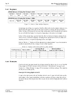
This register is where the 4-bit red/green/blue data value is written/read. With each
successive read or write the internal RGB selector is incremented. Depending on the RGB
Index setting, one to three access of this register will result in the Look-Up Table Address
incrementing.
4.2 Look-Up Table (LUT) Organization
Color and monochrome operation is slightly different. Both Look-Up Table schemes are
described here.
• The Look-Up Table treats the value of a pixel as an index into an array of colors or gray
shades. For example, a pixel value of zero would point to the first LUT entry; a pixel
value of 7 would point to the eighth LUT entry.
• The value inside each LUT entry represents the intensity of the given color or gray
shade. This intensity can range in value between 00 and 0Fh.
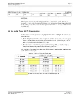
The following table shows how many elements from each Look-Up Table index are used
at the different color depths.
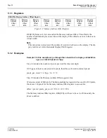
REG[17h] Look-Up Table Data Register Read/Write
n/a
n/a
n/a
n/a
LUT Data
Bit 3
LUT Data
Bit 2
LUT Data
Bit 1
LUT Data
Bit 0
Table 4-4: Look-Up Table Configurations
Display Mode
4-Bit Wide Look-Up Table
Red
Green
Blue
1 Bpp Gray
4 banks of 2
2 Bpp Gray
4 banks of 4
4 Bpp Gray
1 bank of 16
1 Bpp Color
4 banks of 2
4 banks of 2
4 banks of 2
2 Bpp Color
4 banks of 4
4 banks of 4
4 banks of 4
4 Bpp Color
1 bank of 16
1 bank of 16
1 bank of 16
8 Bpp Color
2 banks of 8
2 banks of 8
4 banks of 4
Indicates the Look-Up Table is not used for that display mode
*

