3.4. Other codes
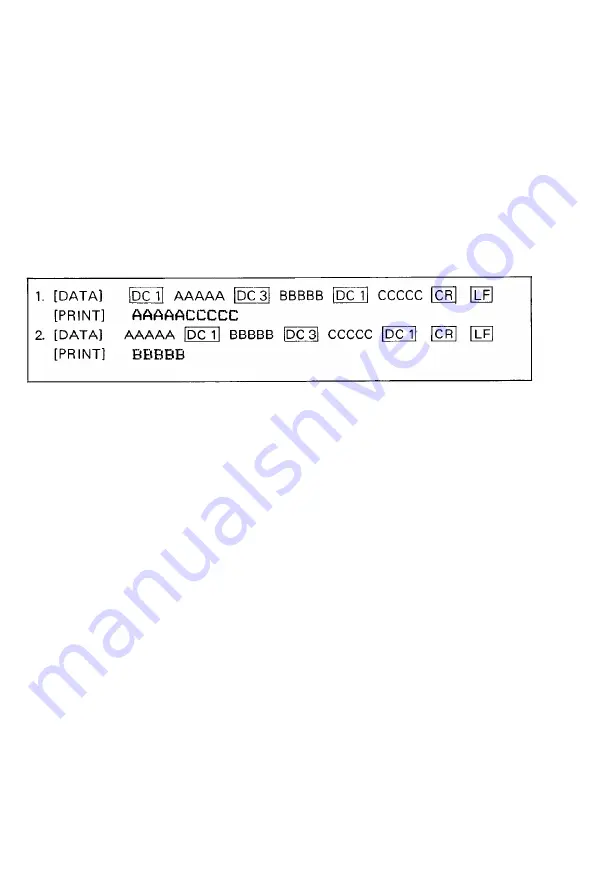
(1) DC 1 (Device Control 1)
The DC 1 code places the Printer in the Selected state. It enables the Printer to
receive data.
With the Printer in the Selected state, if the DC 1 code is input during data
transfer, all data stored before the DC 1 code is ignored.
(2) DC 3 (Device Control 3)
The DC 3 code places the Printer in the Deselected state. In other words, it
disables the Printer to receive data. Once the Printer is put in the Deselected
state by the DC 3 code, the Printer will not revert to the Selected state unless
the DC 1 code is input again.
NOTE: When the DC 1 and DC 3 codes are used, the DIP switch pin 1-8 on the control
circuit board should be in the “OFF” position.
(3)
ESC 8 (Escape 8) (to ignore the Paper End detector)
The ESC 8 code makes it possible to transmit data even if there is no paper in
the Printer. Since this code causes the PE signal to be ignored, data may be
printed to the last page of the form without waste of paper. With the DIP
switch pin l-6 on the control circuit board set in the ON position, the Printer
is placed in the ESC 8 condition upon application of power.
(4)
ESC 9 (Escape 9)
This code cancels the ESC 8 condition, and reinstates the PE signal. Therefore,
the Printer cannot receive data when there is no paper. With the DIP switch
pin l-6 set in the OFF position, the Printer is placed in the ESC 9 condition
upon application of power.
(5)
BEL
(Bell)
When the BE L code is input, the buzzer sounds for about 1 second.
Arbitrary use of this code is recommended to arouse the attention of the
operator.
(6) BS (Back Space)
The BS code cancels the data immediately preceding this code in the Text
Mode. In other words, one byte data stored prior to the BS code is cleared
from the print buffer, as though that data has not been transferred from the
host computer. Note that this code is valid only in the Text Mode.
- 6 6 -
Summary of Contents for MX-80 F/T Type II
Page 1: ...M X 8 0 EPSON DOT MATRIX PRINTER TYPE II Operation Manual EPSON P8190014 2 ...
Page 22: ... 1 6 ...
Page 41: ... 3 5 ...
Page 44: ...1 3 Printer initial check Take the following steps and become familiar with the Printer 3 8 ...
Page 55: ...Fig 57 Setting Form Length per Page 4 9 ...
Page 56: ...Fig 58 Setting Number of Columns per Line 5 0 ...
Page 57: ...Fig 59 Setting Skip over Perforation Function 5 1 ...
Page 80: ... 2 Normal density bit image printing 74 ...
Page 89: ......
Page 90: ...Fig Al 2 Driver Circuit Diagram 8 5 ...
Page 96: ......
Page 97: ...APPENDIX 4 Character Fonts 92 ...
Page 98: ...NOTE Numbers represent Hex code 93 ...
Page 99: ... 94 ...
Page 100: ... 95 ...
Page 101: ...APPENDIX 5 Control Codes ...


