


E
E
p
p
s
s
o
o
n
n
E
E
T
T
-
-
4
4
5
5
5
5
0
0
,
,
L
L
6
6
5
5
5
5
/
/
6
6
5
5
6
6
R
R
e
e
v
v
i
i
s
s
i
i
o
o
n
n
B
B
D
D
i
i
s
s
a
a
s
s
s
s
e
e
m
m
b
b
l
l
y
y
/
/
R
R
e
e
a
a
s
s
s
s
e
e
m
m
b
b
l
l
y
y
D
D
e
e
t
t
a
a
i
i
l
l
e
e
d
d
D
D
i
i
s
s
a
a
s
s
s
s
e
e
m
m
b
b
l
l
y
y
/
/
R
R
e
e
a
a
s
s
s
s
e
e
m
m
b
b
l
l
y
y
P
P
r
r
o
o
c
c
e
e
d
d
u
u
r
r
e
e
f
f
o
o
r
r
e
e
a
a
c
c
h
h
P
P
a
a
r
r
t
t
/
/
U
U
n
n
i
i
t
t
5
5
0
0
Confidential
Confidential
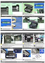
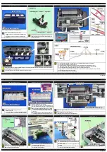
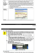
Main Board Shield Plate Upper
Main Board Shield Plate Upper
Tighten the screws in the order indicated in the figure above.
Tighten the screws in the order indicated in the figure above.
Main Board Shield Plate Upper
Main Board Shield Plate Upper
1
1
C.B.S-TITE SCREW 3x6 F/ZN-3C (4 ± 1
C.B.S-TITE SCREW 3x6 F/ZN-3C (4 ± 1 kgf
kgf
··
cm)
cm)
C.P SCREW 3x4 F/ZN-3C (4 ± 1 kgf
C.P SCREW 3x4 F/ZN-3C (4 ± 1 kgf
··
cm)
cm)
C.B.S-TITE SCREW 3x10 F/ZN-3C (4 ± 1 kgf
C.B.S-TITE SCREW 3x10 F/ZN-3C (4 ± 1 kgf
··
cm)
cm)
Bottom
Bottom
5
5
2
2
3
3
4
4
6
6
7
7
EJ Roller Gear
EJ Roller Gear
Insert the EJ Roller Gear fully into the EJ Roller to make it secured
Insert the EJ Roller Gear fully into the EJ Roller to make it secured
completely.
completely.
EJ Roller
EJ Roller
EJ Roller Gear
EJ Roller Gear
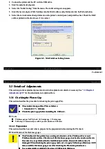
Star Wheel Holder Assy
Star Wheel Holder Assy
Attach the EJ grounding spring as shown above.
Attach the EJ grounding spring as shown above.
Tighten the screws in the order indicated in the figure above.
Tighten the screws in the order indicated in the figure above.
Star Wheel Holder Assy
Star Wheel Holder Assy
EJ grounding spring
EJ grounding spring
80 digit side
80 digit side
C.B.P-TITE(SP
C.B.P-TITE(SP-1) SCREW 3x12 F/ZN-3C (6 ±
-1) SCREW 3x12 F/ZN-3C (6 ± 1 kgf
1 kgf
··
cm)
cm)
1
1
2
2
PF Roller
PF Roller
Attach the PF Roller grounding spring as shown above.
Attach the PF Roller grounding spring as shown above.
PF Roller grounding spring
PF Roller grounding spring
PF Roller
PF Roller
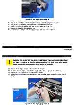
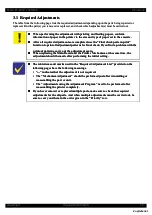
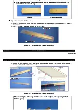
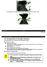
Main Frame Assy
Main Frame Assy
Remove the PW Sensor, CR Unit and so on without removing the Main Frame Assy as much as possible when removing them because section B on
Remove the PW Sensor, CR Unit and so on without removing the Main Frame Assy as much as possible when removing them because section B on
the Paper Guide Front Assy is deformed when the screw of 80-digits side is removed.
the Paper Guide Front Assy is deformed when the screw of 80-digits side is removed.
If removing the Main Frame Assy, remove it as follows.
If removing the Main Frame Assy, remove it as follows.
1.
1. Move the CR Unit to the end of the 80-d
Move the CR Unit to the end of the 80-digit side, and deta
igit side, and detach the rails (x 2) of the CR Unit fro
ch the rails (x 2) of the CR Unit from the guides on the Fron
m the guides on the Front Frame.
t Frame.
2.
2. Remove the D/E Leve
Remove the D/E Lever by sliding it to the 0-dig
r by sliding it to the 0-digit side and alignin
it side and aligning the shape of the lever wit
g the shape of the lever with the cutout on the Main Fram
h the cutout on the Main Frame Assy.
e Assy.
3.
3. Release the C
Release the CR Motor cabl
R Motor cable from the ho
e from the hook on the Main F
ok on the Main Frame Ass
rame Assy.
y. (p 51)
(p 51)
4.
4. Release th
Release the Head FF
e Head FFC from t
C from the hook o
he hook on the Fro
n the Front Fram
nt Frame.
e. (p 52)
(p 52)
5.
5. Remove the scr
Remove the screws (x 2) that secu
ews (x 2) that secure the Main Frame As
re the Main Frame Assy, and remo
sy, and remove the Main Frame As
ve the Main Frame Assy.
sy.
Rear
Rear
D/E Lever
D/E Lever
Cutout
Cutout
CR unit
CR unit
C.B.P-TITE SCREW 3x10 F/ZN-3C (6 ± 1
C.B.P-TITE SCREW 3x10 F/ZN-3C (6 ± 1 kgf
kgf
··
cm)
cm)
Bottom of CR Unit
Bottom of CR Unit
Rail
Rail
80 digit side
80 digit side
Guide
Guide
Nozzle plate surface of
Nozzle plate surface of Printhead
Printhead
Main Frame Assy
Main Frame Assy
Section B
Section B
1
1
2
2
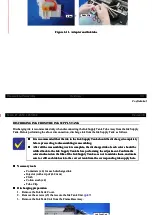
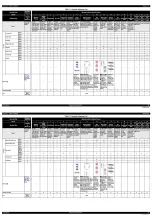
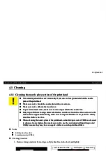
Ink System
Ink System
When routing the Ink Tube, be careful about the following.
When routing the Ink Tube, be careful about the following.
Route through the ribs (x 3) on the Frame Base Assy.
Route through the ribs (x 3) on the Frame Base Assy.
Make sure that the Ink Tube is not folded in any part.
Make sure that the Ink Tube is not folded in any part.
Align the marking of the ink tube with the hole of the Frame
Align the marking of the ink tube with the hole of the Frame
Base Assy.
Base Assy.
Ink Tube
Ink Tube
Rib
Rib
Align the marking
Align the marking
Right Frame
Right Frame
When reassembling, align the hooks on the Main Frame/Front
When reassembling, align the hooks on the Main Frame/Front
Frame with the positioning holes on the Right Frame.
Frame with the positioning holes on the Right Frame.
Right Frame
Right Frame
C.B.S-TITE SCREW 3x6 F/ZN-3C (4 ± 1
C.B.S-TITE SCREW 3x6 F/ZN-3C (4 ± 1 kgf
kgf
··
cm)
cm)
C.B.S-TITE SCREW 3x6 F/ZN-3C (8 ± 1
C.B.S-TITE SCREW 3x6 F/ZN-3C (8 ± 1 kgf
kgf
··
cm)
cm)
Hook and Hole
Hook and Hole
E
E
p
p
s
s
o
o
n
n
E
E
T
T
-
-
4
4
5
5
5
5
0
0
,
,
L
L
6
6
5
5
5
5
/
/
6
6
5
5
6
6
R
R
e
e
v
v
i
i
s
s
i
i
o
o
n
n
B
B
D
D
i
i
s
s
a
a
s
s
s
s
e
e
m
m
b
b
l
l
y
y
/
/
R
R
e
e
a
a
s
s
s
s
e
e
m
m
b
b
l
l
y
y
R
R
o
o
u
u
t
t
i
i
n
n
g
g
F
F
F
F
C
C
s
s
/
/
c
c
a
a
b
b
l
l
e
e
s
s
5
5
1
1
Confidential
Confidential
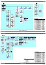
2.5
2.5 Rou
Routin
ting FFC
g FFCs/c
s/cabl
ables
es
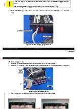
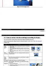
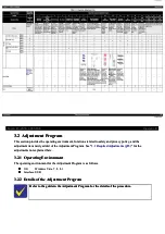
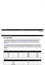
ADF/Scanner Unit
ADF/Scanner Unit
Connect the Scanner FFC, ADF PE Sensor cable, and grounding wire to their
Connect the Scanner FFC, ADF PE Sensor cable, and grounding wire to their
connectors on the Main Board Assy as shown above.
connectors on the Main Board Assy as shown above.
ADF/Scanner Unit
ADF/Scanner Unit
Main Board Assy
Main Board Assy
Scanner FFC
Scanner FFC
Grounding wire
Grounding wire
ADF PE Sensor cable
ADF PE Sensor cable
ADF Frame Assy
ADF Frame Assy
Route the ADF PE Sensor cable through the rib and then through the hole on
Route the ADF PE Sensor cable through the rib and then through the hole on
the bottom of the ADF Base, and then connect it to the ADF PE Sensor on the
the bottom of the ADF Base, and then connect it to the ADF PE Sensor on the
ADF Frame Assy.
ADF Frame Assy.
ADF Frame Assy
ADF Frame Assy
ADF PE Sensor
ADF PE Sensor
ADF PE Sensor
ADF PE Sensor
cable
cable
ADF PE Sensor cable
ADF PE Sensor cable
H
Ho
ollee
R
Riib
b
A
AD
DF
F
B
Ba
assee
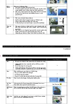
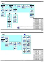
Scanner Housing Lower Assy
Scanner Housing Lower Assy
Scanner FFC
Scanner FFC
••
Route th
Route through
rough the rib
the ribs (x 1
s (x 11) on
1) on the Scan
the Scanner Ho
ner Housing
using Lower A
Lower Assy.
ssy.
••
Set the ferr
Set the ferrite core in the po
ite core in the position sh
sition shown below
own below and secur
and secure it with doubl
e it with double-sided ta
e-sided tape.
pe.
Scanner grounding (GND) wire
Scanner grounding (GND) wire
••
Set the
Set the ground
grounding (G
ing (GND) ter
ND) terminal i
minal in the p
n the position
osition shown
shown above.
above.
••
Route thro
Route through the cabl
ugh the cable guides (x 3
e guides (x 3), then thro
), then through the hole on t
ugh the hole on the Scanne
he Scanner Housing L
r Housing Lower Ass
ower Assy.
y.
Scanner Housing Lower Assy
Scanner Housing Lower Assy
Rib
Rib
Cable guide
Cable guide
S
Scca
an
nn
neer F
r FF
FC
C
F
Feerrrriitte c
e co
orree
S
Scca
an
nn
neer
r G
GN
ND
D w
wiirree
G
GN
ND
D tteerrm
miin
na
all
Hole
Hole
Double-sided tape
Double-sided tape
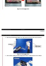
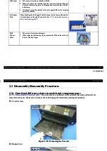
Scanner Carriage Unit
Scanner Carriage Unit
Route the Scanner FFC through the ribs (x 2) on the Scanner Carriage Unit.
Route the Scanner FFC through the ribs (x 2) on the Scanner Carriage Unit.
Route the Scanner FFC through the FFC guide and connect to CN1 on
Route the Scanner FFC through the FFC guide and connect to CN1 on
Scanner encoder sensor
Scanner encoder sensor
Connect the Scanner FFC to the CIS Module aligning with the folds on the FFC.
Connect the Scanner FFC to the CIS Module aligning with the folds on the FFC.
Rib
Rib
Scanner Carriage Unit
Scanner Carriage Unit
CIS Module
CIS Module
Scanner FFC
Scanner FFC
FFC guide
FFC guide
Scanner encoder sensor
Scanner encoder sensor
Scanner FFC
Scanner FFC
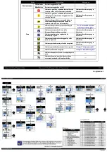
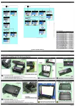
CR Motor cable
CR Motor cable
Route through the hooks (x 9) on the Printer Mechanism, and connect to the
Route through the hooks (x 9) on the Printer Mechanism, and connect to the
connector (CN9) on the Main Board.
connector (CN9) on the Main Board.
Hook
Hook
CR Motor
CR Motor
CR Motor cable
CR Motor cable
Main Board
Main Board
CR Motor cable
CR Motor cable
C R
C R Mo
Mot o
t or
r ca
cabl
blee
P r
P rin
int e
t er
r Me
Mech
cha n
a nis
ism
m
Speaker cable/Panel FFC
Speaker cable/Panel FFC
Speaker cable
Speaker cable
Route through the rib on the Frame Base Assy.
Route through the rib on the Frame Base Assy.
Panel FFC
Panel FFC
Route behind the ribs (x 4) on the Frame Base Assy and secure at the points (x2) above with double-sided tape.
Route behind the ribs (x 4) on the Frame Base Assy and secure at the points (x2) above with double-sided tape.
Rib
Rib
Double-sided tape
Double-sided tape
Frame Base Assy
Frame Base Assy
Panel FFC
Panel FFC
Rear
Rear
Speaker cable
Speaker cable
Panel FFC
Panel FFC