Epson Stylus SX230 series / SX235W series / SX430W series / SX440W series
Revision B
Disassembly/Reassembly
Detailed Disassembly/Reassembly Procedure for each Part/Unit
36
Confidential
Printhead
When removing/replacing the Printhead, be sure the CR Unit is at the “ink cartridge exchange position” shown above. Otherwise, the Main Frame
may be deformed by applying force perpendicularly when tightening the screws and it may affect print quality.
The “ink cartridge exchange position” is also indicated by the Ink Position Label attached on the Housing Rear. See
for the
position of the Ink Position Label.
Tighten the screws of the Printhead in the order indicated in the figure above while pressing the Printhead in the direction of the arrow.
Bottom of CR Unit
Protrusion of CR Unit
Section A
Star Wheel Holder Assy
C.B.P-TITE SCREW 2.5x8 F/ZN-3C (3 ± 1 kgf·cm)
Printhead
CR Unit (ink cartridge exchange position)
1
2
3
Ink cartridge exchange position: when the protrusion of the CR Unit is
on the section A of the Star Wheel Holder Assy.
Do not remove/replace the Printhead other than under this condition in
order to prevent the Main Frame from being deformed.
Star Wheel Holder Assy
Main Frame
Main Frame Assy
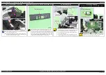
Before installing the Main Frame Assy, shift the Change Lever back to the rear.
When installing the Main Frame Assy, make sure of the following.
•
The Change Lever must not interfere with the Main Frame.
•
The above shown ribs and grooves, positioning holes and dowels are correctly aligned.
•
The section A of the Main Frame Assy is not deformed.
Tighten the screws in the order indicated in the figure above.
3
5
Align the screw holes of Main
Frame and PF Motor Frame.
PF Motor Frame
Main Frame
4
Tighten screw while pressing Main
Frame in the direction of the arrow.
C.B.P-TITE SCREW 3x10 F/ZN-3C (6 ± 1 kgf·cm)
C.B.S-TITE SCREW 3x6 F/ZN-3C (6 ± 1 kgf·cm)
1
2
Main Frame Assy
Change Lever must not
interfere with Main Frame.
Rib and groove
Positioning hole and dowel
Section A
PF Encoder Sensor/ PF Scale
Do not reuse the removed PF Scale and make sure to replace it with a new one when removing it.
When installing the PF Scale, it is pressed into the PF Roller, therefore, the removed one is deformed. If it is re-installed to the printer, it does not
rotate properly and the paper feed accuracy may be reduced.
When installing the PF Scale to the PF Roller, press the PF Scale into the PF Roller vertically.
After installing the PF Encoder Sensor, confirm the PF Scale does not touch the PF Encoder Sensor.
PF Scale
PF Encoder Sensor
PF Roller
PF Encoder Sensor
PF Scale
PF Roller
Pump Unit
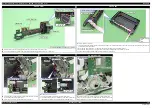
When installing the Pump Unit, follow the procedure below in order to prevent ink suction failure.
1. Route the Pump Tube A through the hole of the Frame Base.
2. Install the Pump Unit to the Frame Base, and route the Pump Tube A through the ribs of the Frame Base with their dashed line facing upward.
3. Secure the Pump Unit to the Frame Base with the screw (x1).
4. Route the Pump Tube B through the ribs of the Pump Unit and Frame Base, and insert it to the hole of the Frame Base up to the marking
(8
±
1 mm from tube end).
Step 4
Pump
Tube B
Marking
8 ± 1 mm
Hole of Frame Base
Hole of
Frame Base
Pump
Tube A
Step 1-2
Pump Unit
Route Pump Tube A through ribs of Frame
Base with their dashed line facing upward.
Insert Pump Tube B up to the marking (8 ± 1 mm
from tube end) to the hole of Frame Base.
C.B.P-TITE SCREW 3x10 F/ZN-3C (6 ± 1 kgf·cm)
Step 3
Frame Base
Rib
Summary of Contents for Epson Stylus NX330
Page 9: ...Confidential CHAPTER 1 TROUBLESHOOTING ...
Page 19: ...Confidential CHAPTER 2 DISASSEMBLY REASSEMBLY ...
Page 41: ...Confidential CHAPTER 3 ADJUSTMENT ...
Page 52: ...Confidential CHAPTER 4 MAINTENANCE ...
Page 58: ...Confidential CHAPTER 5 REFURBISHMENT ...


