background image

42

12

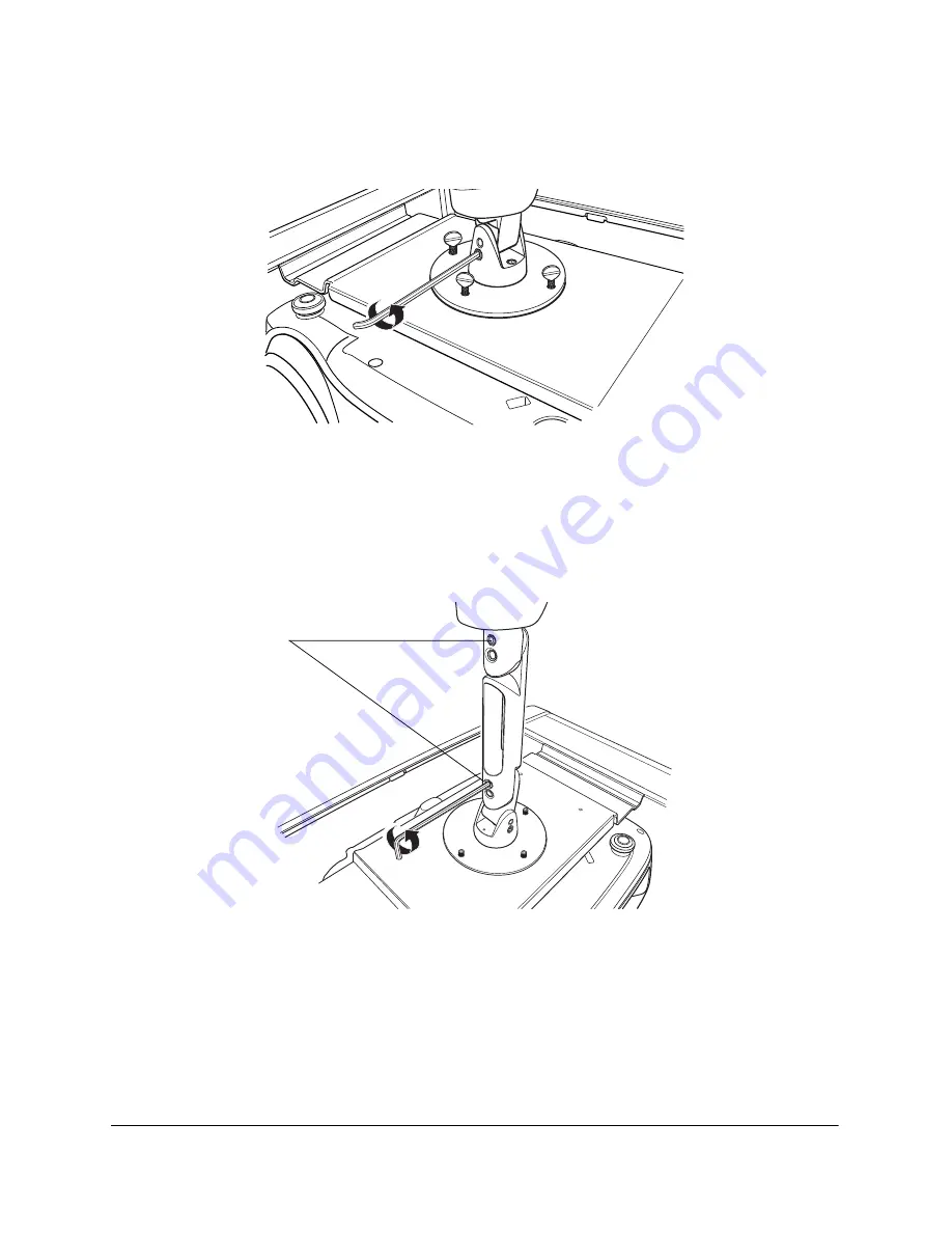
Make sure the projector is not tilted sideways. If the projector is tilted to one side, loosen the set screw on 
the front of the mounting bracket (shown below) and adjust the projector so it’s level. Tighten the set screw 
when done.

13

If you’ve used the extension arm, make sure the projector is not tilted down toward the screen. Loosen the 
set screws on the side of the arm and adjust it so it’s straight. Tighten the set screws when done.

Note 

For most installations, the projector should be mounted level (not tilted down toward the screen). If you find that the 
image is too high or too low, you can reposition it using the vertical lens shift dial. If you have the PowerLite Home 
Cinema 720, you can tilt the projector down if necessary and use the keystone adjustment to correct the resulting 
image distortion (see “Adjusting the Image” on page 51).

To level the projector, 
loosen these set screws 
and adjust arm

Summary of Contents for Ensemble HD

Page 1: ...Installation Guide ...

Page 2: ...ons to this product or excluding the U S failure to strictly comply with Seiko Epson Corporation s operating and maintenance instructions Trademarks Epson is a registered trademark and Epson Exceed Your Vision is a logomark of Seiko Epson Corporation PowerLite and PrivateLine are registered trademarks Ensemble HD is a trademark and Epson Store is a service mark of Epson America Inc The DVD Video l...

Page 3: ... Option 1 21 Attach the Mounting Assembly to the Ceiling Option 2 24 Connect the Cables to the Screen 26 Lift the Screen onto the Mounting Brackets 29 Installing the Projector 31 Position the Ceiling Mount 32 Attach the Extension Arm Optional 35 Install the Ceiling Mount 37 Mount the Projector 38 Connecting and Routing the Cables 43 Unpack the Wire Management Tracks 43 Install the Tracks and Conne...

Page 4: ...tance 59 Equalize the Speaker Output 60 Adjust the Subwoofer Output 60 After Completing the Installation 62 Using Additional Components 63 Connecting External Video Devices 63 Connecting Another Subwoofer 68 Connecting an Antenna 69 Using a Third party Universal Remote Control 71 ...

Page 5: ... The 10 inch subwoofer with built in amplifier provides rich bass and powers all the speakers in the system The included stand lets you place the subwoofer AV controller and other components neatly in one place AV controller The AV controller includes a built in DVD player and delivers high definition video and surround sound output You can also connect existing AV components to it such as a cable...

Page 6: ...uctions in the literature accompanying the appliance 1 Read these instructions 2 Keep these instructions 3 Heed all warnings 4 Follow all instructions 5 Do not use this apparatus near water 6 Clean only with dry cloth 7 Do not block any ventilation openings Install in accordance with the manufacturer s instructions 8 Do not install near any heat sources such as radiators heat registers stoves or o...

Page 7: ...studs wallboard or plasterboard or cinder block wall construction Do not attempt to use hollow wall anchors screws or similar mounting hardware to mount the projector or screen to wallboard or plasterboard The projector and screen cannot be safely mounted like that You must mount the projector and screen to wooden studs joists or to a solid concrete surface as outlined in these instructions When i...

Page 8: ...na discharge unit connection to grounding electrodes and requirements for the grounding electrode See the drawing below An outside antenna system should not be located in the vicinity of overhead power lines or other electric light or power circuits or where it can fall into such power lines or circuits When installing an outside antenna system extreme care should be taken to keep from touching su...

Page 9: ...riginal part Unauthorized substitutions may result in fire electric shock or other hazards When closing the screen be careful not to pinch your fingers where the screen closes against the case Do not touch the white part of the screen with your hands Oil from your skin could damage it Never look into the projector lens when the lamp is turned on The bright light can damage your eyes Never let chil...

Page 10: ...Projector enclosure and rear surround speakers Box 3 AV Cables see Included Cables on page 11 for details and HDMI repeater Box 4 Screen and screen mounting hardware Wire management tracks 8 feet long Wire management connector pieces seam covers and drywall screws Box 5 Subwoofer AC power cables Box 6 Subwoofer stand Box 7 Speaker grilles for screen Note The included hardware is designed to let yo...

Page 11: ...rough the wall and ceiling or where you want to place the projector at a greater distance from the screen You can purchase these accessories from an Epson authorized reseller To find the nearest reseller call 800 GO EPSON 800 463 7766 To purchase online visit www EnsembleHD com U S sales only Cable connection Cable name Length From power outlet to subwoofer Main power cord 6 feet 1 8 m From AV equ...

Page 12: ...This is the fastest way of speaking to a live representative and it s free This service is available 6 AM to 6 PM Pacific Time Monday through Friday for the duration of your warranty period You may also speak with a support specialist by dialing 562 276 4394 6 AM to 6 PM Pacific Time Monday through Friday Days and hours of support are subject to change without notice Toll or long distance charges ...

Page 13: ...e advice concerning construction practices or building codes in your area Screen image 1 Plan the screen location and room layout The seating area should be in the middle and the projector toward the rear See page 14 3 Install the ceiling mount and projector Use a stud finder to locate wooden joists on which to mount the projector See page 31 4 Connect the equipment and route cables Use the includ...

Page 14: ...Warning Do not route the included power cables through the wall or ceiling They are not rated for this purpose Deliberate mis installation could result in fire or other safety hazards Laying Out the Home Theater The home theater should be arranged as shown below with the projector and screen at opposite ends of the room and the seating area in the middle For a successful installation the room must...

Page 15: ...hes from the top of its enclosure This provides a 3 inch black border at the top Additional black drop length lets you lower the screen as much as 70 inches When you mount the screen on the wall it s recommended that you place it from 2 to 22 inches from the ceiling This produces the best sound quality and helps ensure that the image can be successfully positioned on the screen You may be able to ...

Page 16: ...ts in the system you should place it within 6 feet 1 8 m of a power outlet You should also place it within 9 feet 2 7 m of cabling distance from the AV controller and 33 feet 10 m of cabling distance from the screen see Routing the Cables in the next section An optional stand is included in which the subwoofer and other components can be placed If you choose to use it you can place the AV controll...

Page 17: ...ant so they can be routed through a wall an attic or the space above your ceiling If you choose this option plug the AC power cables for the screen and projector directly into nearby electrical outlets If no outlets are available contact a licensed electrician to have them installed Warning Do not route the included power cables through the wall or ceiling They are not rated for this purpose Delib...

Page 18: ...LEVEL PWR ON MODE SUB OUT BASS CONTOUR CONTROL 98 99 Rear surround speakers L C R speaker connectors AV data cable Control cable HDMI cable HDMI repeater and power supply Control cable HDMI cable 110 VAC power cable Main power cord 110 VAC power cables Speaker cable Speaker cable Projector Motorized screen Subwoofer AV Controller ...

Page 19: ...een without speaker grilles Alignment bar Wall mounting brackets Ceiling mounting brackets Mounting hardware to mount the screen to wooden studs joists or a solid concrete surface Ceiling mounting brackets Screen without speaker grilles Wood screws 8 pieces Alignment bar TOGGLER brand wall anchors 2 pieces in bag Wall mounting brackets Concrete anchors and anchor bolts 8 pieces each Mounting brack...

Page 20: ... that protect the speakers during shipping 2 Attach the speaker grilles Hook each grille into the lip underneath the screen housing where the screen itself comes out Then attach the grille on top with the two screws that came with it Caution Be careful not to damage the grilles when handling them Do not hold the screen by the grilles which are fragile and can be easily dented Lift the screen only ...

Page 21: ...brackets to the wall as shown in step 5 2 Slide the wall mounting brackets onto the alignment bar as shown below Insert the 4 small screws into the face of the brackets Loosely tighten the screws to keep the brackets from sliding off the bar 3 Mark the wall to indicate where you will attach the mounting hardware First determine how far the top of the screen housing should be from the ceiling For a...

Page 22: ...act center of each stud Warning You must find the exact center of each stud or you won t be able to attach the screen securely Note The middle bracket doesn t have to be attached to a stud It must however be aligned with the middle of the screen See step 9 Distance from ceiling plus 3 inches Do not install alignment bar not shown above this line Locate studs where you can attach the end brackets S...

Page 23: ...the middle bracket so it s aligned with the middle of the screen The set screw in the middle of the screen must engage with the bracket 9 If the middle bracket aligns with the center of a stud see drawing below attach it to the wall with two wood screws otherwise use two Toggler wall anchors included If necessary you can move the bracket slightly left or right to align the holes with a stud as lon...

Page 24: ... want to hang the screen Hold the mounting assembly against the ceiling and mark its approximate location 3 Use a stud finder to locate three joists one near each end of the mounting assembly and one near the middle Joists are normally spaced 16 inches on center Mark the exact center of each joist Warning You must find the exact center of the joist or you won t be able to attach the screen securel...

Page 25: ...t to the ceiling with two wood screws otherwise use two Toggler anchors If necessary you can move the bracket slightly left or right to align the holes with a joist as long as at least part of the bracket remains aligned with the middle of the screen Important At least part of the bracket must align with the middle of the screen 10 Tighten the two screws on the face of the bracket to secure it to ...

Page 26: ...t go from the screen to the projector should leave the screen from the middle Let the loose ends of the cables hang out of the screen housing when you re done connecting them Do not connect them to the projector subwoofer or AV controller yet 1 Locate AC CABLE 2 packed in the AC power cable box inside box 5 with the subwoofer 2 Connect AC CABLE 2 to the control box inside the screen as shown below...

Page 27: ...or 6 Place one end of the Video Cable near the middle of the screen You will connect it later 7 Locate AC CABLE 3 Y shaped cable which is packed in the AC power cable box inside box 5 with the subwoofer Note Let the loose ends of the cables connected in the following steps hang out from the middle of the screen You will connect them later To AV controller do not connect yet Cables inside screen To...

Page 28: ...r supply 10 Connect power supply for the HDMI repeater to the power cable as shown above 11 Connect the 4 pin connector of the Speaker Cable to the unconnected speaker cable inside the screen 12 Connect the male end of the Control Cable to the RS 232 port as shown below Tighten the thumbscrews on the connector to secure it in place To projector do not connect yet To HDMI repeater To projector do n...

Page 29: ...of excess cable near the projector you may be able to tuck some of the cable under the long cable cover shown below Lift the Screen onto the Mounting Brackets Note You may wish to attach the wire management tracks to your wall and ceiling first see Connecting and Routing the Cables on page 43 It is easier to attach the tracks near the screen before the screen has been mounted Return to this sectio...

Page 30: ...een might not have engaged with one or more of the brackets 4 If the screen is mounted on the ceiling make sure the front of the casing doesn t tilt downward or the screen fabric will rub on the casing when it goes up or down 5 If necessary slide the screen a few inches left or right to position it correctly 6 Insert the set screw in the bottom center of the screen Use the included Allen wrench to...

Page 31: ... be used to mount the projector to the ceiling as described in these instructions The ceiling plate makes the installation more secure and gives you greater flexibility in positioning the projector For example you can use the plate to position the projector anywhere between two ceiling joists rather than directly on a joist This lets you align the projector with the exact middle of the screen If y...

Page 32: ... total cabling distance from the connectors inside the screen to the ports in back of the projector does not exceed 23 feet 7 m Otherwise the cables won t reach the required distance Factors that increase the required cabling distance include routing the cables in a manner other than a straight path installing the cables inside the wall or ceiling using the projector extension arm mounting the pro...

Page 33: ... use the horizontal lens shift dial to position the image on the screen If you position it off center by more than that the vertical up down lens shift adjustment will be limited Conversely if you don t need to use the projector s full vertical lens shift then you can position the lens more than 8 inches off center if necessary Align ceiling mount with screen s center Try to keep lens within 8 inc...

Page 34: ...n Warning Use a stud finder to locate the center of the first joist You must find its exact center to attach the plate securely Tip With a second person s help you can mark the second joist by holding the plate against the ceiling Carefully align the plate with the mark that indicates the center of the first joist then mark the second joist at the location shown Joists run toward screen Screen Mar...

Page 35: ...a clean appearance and makes the projector less likely to be bumped into In some cases however you may want to attach the included extension arm which lowers the projector by about 8 inches This may help for example if you have track lighting that would interfere with the projected image or if the screen is mounted lower on the wall and you want to bring the projector down to screen level If your ...

Page 36: ... in step 2 You will do this later when you attach the mounting bracket to the ceiling plate as described in the next section 4 Insert the extension arm into the lower plate and fasten it with the bolt you removed in step 1 5 The mounting bracket with the extension arm is now assembled Continue with the steps in the next section to attach the mounting bracket to the ceiling plate and install it on ...

Page 37: ...late goes on the recessed side of the ceiling plate Before tightening the bolts fully check exactly where the projector will be mounted between your ceiling joists Then use the slots in the ceiling plate to slide the parts to the desired location Tighten the bolts to hold the parts in place 3 Re attach the rest of the mounting bracket using the bolts you removed in step 1 or in the previous sectio...

Page 38: ...rojector s ceiling mount before the projector has been mounted 1 Unpack the projector from the projector box located inside box 1 Keep the lens cap on the projector for now Make sure you have the parts shown below Note Your Ensemble HD system may come with a different projector model than the one shown here The projector box may also include additional parts 2 Save the projector User s Manual and ...

Page 39: ...essing inward pull backward on the same side to separate the cover from the enclosure Repeat on the opposite side 5 If you anticipate having excess cable near the projector install the optional cable cleats on top of the projector enclosure The cleats will let you wrap excess cable around them Attach the cleats with the included screws at the points shown below 1 2 Remove rear cover by pressing in...

Page 40: ...e bottom of the round plate If any of the screws protrude you won t be able to attach the projector Also make sure the pointed part faces toward the screen If necessary grasp the mounting bracket and rotate it so that it faces the correct direction You may need to loosen the two bolts at the top to rotate the assembly shown in step 8 8 Securely tighten the two bolts at the top of the mounting brac...

Page 41: ...r over your head when mounting it 10 Engage the projector with the ceiling mount then rotate it 180 degrees so it faces toward the screen 11 Tighten the three thumb screws Make sure the projector is secure and does not rotate Note Make sure the projector faces the screen squarely Do not be concerned if the lens is positioned off center from the screen If you find that the image is too far left or ...

Page 42: ... on the side of the arm and adjust it so it s straight Tighten the set screws when done Note For most installations the projector should be mounted level not tilted down toward the screen If you find that the image is too high or too low you can reposition it using the vertical lens shift dial If you have the PowerLite Home Cinema 720 you can tilt the projector down if necessary and use the keysto...

Page 43: ...ur ceiling If you choose this option plug the AC power cables for the screen and projector into nearby electrical outlets If no outlets are available contact a licensed electrician to have them installed Warning Do not route the included power cables through the wall or ceiling They are not rated for this purpose Deliberate mis installation could result in fire or other safety hazards Unpack the W...

Page 44: ...ks and connector pieces to your wall and ceiling using the adhesive backing To orient the parts correctly take note of the following When connecting two tracks together you need to make sure the channels inside the tracks line up where the pieces meet Colors are marked on the ends of the tracks to assist with this You may have to rotate a length of track end for end to make the channels and colors...

Page 45: ... 5 Press the covers in place on each track and connector piece If necessary use a hacksaw to cut the covers to desired lengths Tip When using a hacksaw cut the plastic slowly to maintain smooth edges 6 Apply a seam cover to disguise the seam where two pieces meet Remove the adhesive backing from the covers to apply them Connect the Cables to the Projector 1 Before connecting the cables to the proj...

Page 46: ...t the speaker cable to the connectors for the left and right speakers in the projector enclosure Match up the R right and L left labels on the connectors Connect the Cables to the Subwoofer and AV Controller 1 Unpack the subwoofer from box 5 2 Unpack the AV controller from box 1 Video cable HDMI port Control cable RS 232C port AC cable Power switch Speaker connectors ...

Page 47: ...to the AV controller Video cable connect to HDMI OUT port Control cable with 3 5 mm stereo mini jack plug connect to IR IN port Caution Be sure to connect the video cable to the HDMI OUT port and the control cable to the IR IN port 47 61 82 FREQ LEVEL PWR ON MODE MASTER POWER SUB OUT BASS CONTOUR CONTROL 98 99 Connect speaker cable here Connect AC cable to either outlet Connect control cable here ...

Page 48: ...ofer Connect the other end to a grounded power outlet in your home Note It is recommended that the Ensemble HD system be powered by a dedicated 20 amp circuit Typical power consumption is about 800 watts 8 Set the MASTER POWER switch to the ON position 9 Set the PWR ON MODE switch to the AUTO position This lets the subwoofer turn on when it detects a signal 10 Wrap any excess cable secure it with ...

Page 49: ...derneath the base should face downward 3 Use the nuts and bolts to connect the side panels to the base Insert the nuts into the holes underneath the base Use a flathead screwdriver if necessary to align the nuts so the bolts thread into them Make sure the side panels face the correct direction the side with more holes should face inward Tighten the bolts with the included Allen wrench Tip You may ...

Page 50: ... You must insert them first before inserting the bolts You may find it easier to connect the shelves if you tilt the stand back 5 Insert the rubber feet into the holes in the base Note The feet help to isolate vibration from the subwoofer 6 Check all bolts to make sure they re securely tightened 7 Slide the subwoofer into the stand making sure its feet align with the rubber pads in the base Insert...

Page 51: ...dy 2 Remove the projector lens cap 3 Make sure the MAIN menu is displayed on the Ensemble HD remote control If necessary press the MAIN button 4 Point the remote control at the screen and press the ON button to turn on the system The screen comes down and the projector and AV controller turn on Note Make sure the remote control remains pointed at the screen until the built in macro finishes turnin...

Page 52: ...o AUTO If the projector doesn t come on make sure the power switch on the back of the projector is in the on position Make sure the lens cap is removed 5 After the screen is lowered remove and discard any protective packing material that was held in place with the screen rolled up Adjust the Screen Position The screen is factory set to come down 55 inches but you can set it to come down as far as ...

Page 53: ...nce the screen is positioned where you want it press S SET to set the screen position 6 Press S UP to raise the screen fully Note You must raise the screen all the way for the new position to take effect 7 Press S DWN re open the screen Verify that it comes down and stops at the correct position Position the Image 1 Press the Pattern button on the projector s remote control This displays an adjust...

Page 54: ...n If you have the PowerLite Home Cinema 720 and you re using the extension arm tilt the projector only if the lens shift dial does not lower the image far enough see Incline Adjustment With the Optional Extension Arm in the next section 4 When you re done positioning the image on the screen re attach the bottom and rear covers to the projector enclosure Note If the image is tilted to one side see ...

Page 55: ... or down so it s positioned correctly on the screen PowerLite Home Cinema 720 If you cannot lower the image far enough using the vertical lens shift dial you can tilt the projector down to position the image on the screen Note Do not perform this adjustment with the PowerLite Home Cinema 1080 It does not have a keystone adjustment for correcting the image distortion that results from tilting the p...

Page 56: ...Projection then press the Select button Select Front Ceiling then press The image is inverted Press the Esc button to return to the Settings menu 5 If the projector is installed above 4900 feet 1500 meters turn on High Altitude Mode so the fan can properly cool the projector Press the Esc button to return to the Settings menu 6 Highlight Display and press For the Startup Screen setting select Off ...

Page 57: ...h the PowerLite Home Cinema 1080 you can press the COL M button repeatedly to change modes 4 The projector s remote control is not needed for making any other adjustments or using the system Remove the batteries from the remote control and keep it in a safe place for future use Color Mode Description Dynamic For projecting the brightest picture available Living Room For watching movies during the ...

Page 58: ...r installation Refer to the chart below which shows the correct setting A B C D or E for various mounting locations Example The screen is mounted on the wall approximately 6 inches from the ceiling Therefore you would select setting C Note If you have a drop ceiling made of porous tiles select setting D no matter where the screen is located 12 A 6 E 6 24 B Distance from wall Distance from ceiling ...

Page 59: ...nd right front speakers Measure and enter the distance from your main seating location to the left and right speakers on the screen Center Distance Adjusts the sound delay from the front center speakers Measure and enter the distance from your main viewing location to the speakers in the middle of the screen Rear Distance Adjusts the sound delay from the rear surround speakers Measure and enter th...

Page 60: ...r for C weight and slow response Use the u or d button to move the test tone to a different speaker Press the u button as needed to keep the test tone from advancing to the next speaker 3 Use the l or r button to change the speaker s output Make sure all the speakers output sound at 75 dB 4 When you re done adjusting the settings press the MENU button to exit the menu system Adjust the Subwoofer O...

Page 61: ...ng area in your theater Flip the PHASE switch back and forth and select the position that offers the best bass sound for your environment and subwoofer location 4 Once you re done selecting the best phase setting set the LEVEL switch on the subwoofer to 0 dB 5 Set the volume level on the AV controller to 0 dB 6 Select the Test Tones chapter on the Ensemble HD DVD 47 61 82 FREQ LEVEL PWR ON MODE SU...

Page 62: ...late the average of all the measured volume levels and draw a line across the graph at that height 10 Calculate the difference in dB between the peak volume and the average volume Then turn the LEVEL switch to the corresponding dB setting based on your calculation This will reduce the volume of the peaking frequency and make it nearly equal to the others After Completing the Installation After set...

Page 63: ...ms see page 68 Antenna to receive AM FM radio broadcasts see page 69 Third party universal remote control see page 71 See the User s Guide for instructions on connecting an audio component such as a tape deck Connecting External Video Devices Connect the video cable from your device to any available port on the back of the AV controller as shown below Caution Avoid connecting or disconnecting any ...

Page 64: ...ing Audio and Video Sources Once you ve connected the audio and video cables you need to tell the Ensemble HD system which audio and video ports to use together You link the audio and video sources together using the Source Assign screen 1 Make sure the MAIN menu is displayed on the remote control If necessary press the MAIN button 2 Point the remote control at the screen and press the MENU button...

Page 65: ...a device not listed below select an unused name such as AUX You can choose from the following labels Device label Description Cable Cable box Sat Satellite receiver HD High definition DVD player DVR Digital video recorder for example TiVo Aux Video game console Video Video cassette recorder Move Enter Exit Menu Sel Video Language Preference Audio Reset Audio Voice Bass Treble Surround Front Distan...

Page 66: ...t the menu system Enabling the Remote Control After connecting a new component you can continue to use its original remote control However it may be more convenient to set up the Ensemble HD remote control to work with it That way you only need to use one remote control You enable the Ensemble HD remote control to recognize the new component by entering a setup code Setup codes are listed in the b...

Page 67: ...65 If you don t see your device on the screen press the PAGE or page up or down button to view more options Press the u or d button to highlight the desired option so it flashes then press the SEL Select button Note Some of the device names DVD RADIO AUDIO and PROJ are already used by the Ensemble HD system and you cannot select them If you re setting up a type of component for which a menu name d...

Page 68: ...l the functions you need When you open the new component s menu you should see all the functions needed to operate it If any commands are missing you can copy them from the component s original remote control For instructions see the section on using advanced remote control features in the User s Guide Note Refer to the manual that came with your component for instructions on using the commands to...

Page 69: ...2 Extend the antenna wire as much as possible Use a nail or thumbtack to secure the end away from your AV equipment and its cables Using the AM Loop Antenna The AM loop antenna is for indoor use 1 Locate the included AM loop antenna packed in the box with the AV controller To prepare it for use fold the base of the antenna under the loop down and toward you Then snap the loop into the base as show...

Page 70: ...ductors location of antenna discharge unit connection to grounding electrodes and requirements for the grounding electrode 3 If you hear audio hum or buzz as a result of grounding the antenna connect a ground loop isolator to the antenna cable close to where it connects to the AV controller This filters out interference caused by the outdoor ground connection Or you can use a coaxial surge protect...

Page 71: ... remote control made by another company to operate the Ensemble HD system For your reference the necessary codes to operate the screen and projector are listed below Not applicable to the PowerLite Home Cinema 1080 projector Screen operation Function Remote ID Remote command Up 0x835f 0x55 Down 0x835f 0x59 Stop 0x835f 0x49 Set 0x835f 0x43 Projector operation Function Remote ID Remote command On 0x...

Reviews: