background image

Corner  Wall

This  allows  you  to  correct  distortion  that  occurs  when  projecting  on  a
surface  with  right  angles,  such  as  a  square  pillar  or  the  corner  of  a  room,
and  adjust  the  amount  of  expansion  and  contraction.

Face  the  projector  directly  opposing  the  screen  with  the  lens  position
moved  to  the  home  position.

s

 "Adjusting  the  Position  of  the  Projected  Image  (Lens  Shift  Adjustment)"

p.37

a

Project  onto  a  surface  with  a  right  angle.

If  a  large  amount  of  adjustment  is  performed,  the  focus  may  not  be
uniform  even  after  making  adjustments.

If  

4K  Enhancement

 is  enabled,  a  message  is  displayed.  Select  

Yes

 to

disable  

4K  Enhancement

.

s


Image

  -  

Image  Enhancement

  -  

4K  Enhancement


p.141

You  can  project  beyond  the  edges  of  the  projected  screen.  However,
once  you  reach  the  limit  of  how  much  correction  can  be  performed,
you   cannot   correct   the   image   any   further.

Use  the  following  to  check  the  adjustment  range  for  the  image.

s

 "Corner  Wall"  

p.261

a

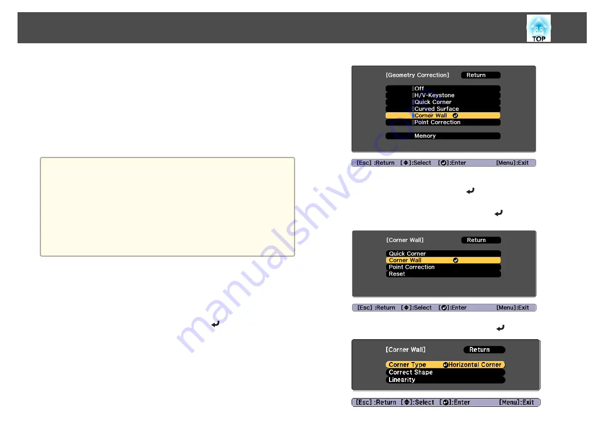
Press  the  [Geometry]  button  while  projecting.

b

Select  

Corner  Wall

,  and  then  press  the  [

]   button.

When  the  message  "If  this  setting  is  changed,  the  image  may  be
distorted."  is  displayed,  press  the  [

]  button  again.

c

Select  

Corner  Wall

,  and  then  press  the  [

]   button.

d

Select  

Corner  Type

,   and   then   press   the   [

]   button.

Adjusting Projected Images

69

Summary of Contents for EB-L30000U

Page 1: ...User s Guide ...

Page 2: ...dicates information that if ignored could possibly result in personal injury or physical damage due to incorrect handling General information indications Attention Indicates procedures which may result in damage or injury if sufficient care is not taken a Indicates additional information and points which may be useful to know regarding a topic s Indicates a page where detailed information regardin...

Page 3: ...base of the projector To prevent the projector from falling thread sufficiently strong wire rope and so on through the ceiling mount and secure to the ceiling Do not place flammable objects in front of the lens If you set the schedule to turn on the projector automatically any flammable objects placed in front of the lens could cause a fire Warning Do not tie the power cord and other connection ca...

Page 4: ...rojector from falling Otherwise it may cause an injury Attention Do not install the projector in a location that is subject to vibration or shock Do not install the projector near a high voltage line or object that generates magnetism Otherwise the projector may not work correctly Do not use or store the projector in a location that is subject to extreme temperatures Also avoid sudden temperature ...

Page 5: ... the top at the four corners Do not remove the feet on the bottom of the projector Except for the projector s parts do not place anything on the projector a The projector can be installed at any angle There is no vertical or horizontal limit to how the projector can be installed We recommend setting the focus zoom and lens shift at least 20 minutes after you start the projection because images are...

Page 6: ...r with the front back side of the projector facing up Make sure that the angle when lifting is 60 degrees or more Attention When attaching directly to the projector Use four commercially available eye bolts M8 ankle length 11 to 16 mm and attach them to the four screw holes for eye bolts When attaching to the handle Use four commercially available eye bolts M10 ankle length 11 mm or more and attac...

Page 7: ...ing the projector If dust or dirt enter the projector projection quality deteriorates and it could cause a malfunction When a high powered laser beams through the surface of the projection lens or the built in camera it can cause a malfunction If the laser beams through the surface of the projection lens or the built in camera block the laser beam with non permeable or incombustible aluminum foil ...

Page 8: ... change the relationship between operation time and decline in brightness in Brightness Settings s Relationship between Brightness Level and light source operation time p 76 a About light source calibration When Run Periodically is set to On for Light Source Calibration every time the usage time reaches 100 hours calibration starts automatically for the light source when the projector is turned of...

Page 9: ...ctor is a Class 1 laser product that complies with the IEC EN60825 1 2014 international standard for lasers Do not disassemble the projector when disposing of it Dispose according to your local or national laws and regulations Hazard Distance according to IEC62471 5 2015 Looking into the lens at distances closer than those indicated here can cause damage to eyesight 5 4 3 2 1 0 0 2 4 6 8 1 3 5 7 6...

Page 10: ...e carrying the projector Check the Transport and Installation Handbook for more information Turn off the power to the projector and disconnect all cables When moving nearby without having to pack up the projector install the lens cap on the lens unit When packing up and transporting the projector remove the lens unit and install the protective cap on the lens unit installation section Enclose the ...

Page 11: ...ing and Loading Lens Adjustment Values 42 ID Settings 43 Set the projector ID 43 Checking the projector ID 44 Setting the remote control ID 44 Setting the Time 44 Other Settings 46 Settings related to basic operations 46 Settings related to display 46 Connecting Equipment 48 Connecting a Computer 48 Connecting Image Sources 50 Connecting to an External Monitor 52 Connecting a LAN Cable 53 Connecti...

Page 12: ...ting conditions for auto adjustment functions 100 Using the Stacking Function of Geometry Correction Assist 101 Operating conditions for auto adjustment functions 101 Projection Functions 103 Projecting Two Images Simultaneously Split Screen 103 Input Sources for Split Screen Projection 103 Operating procedures 103 Restrictions during split screen projection 105 Hiding the Image Temporarily Shutte...

Page 13: ...aving settings to the USB flash drive 166 Reflecting saved settings to other projectors 168 Setup by Connecting the Computer and Projector with a USB Cable 169 Saving settings to a computer 169 Reflecting saved settings to other projectors 171 When Setup Fails 172 Troubleshooting Using the Help 174 Reading the Indicators 175 Understanding the Status Information 182 Checking the Status 182 Understa...

Page 14: ...mity 226 Appendix Monitoring and Controlling 230 Epson Projector Management 230 Changing Settings Using a Web Browser Epson Web Control 230 Displaying the Epson Web Control Screen 230 Basic Control Screen 232 OSD Control Pad Screen 232 Lens Control Screen 233 Status Information Screen 235 Remote Camera Access Screen 235 Using the Mail Notification Function to Report Problems 238 Reading error noti...

Page 15: ...SDI 268 Specifications 270 Projector General Specifications 270 Appearance 275 General Notes 277 About Notations 277 Trademarks and Copyrights 277 List of Safety Symbols 279 Index 281 Contents 15 ...

Page 16: ...Introduction This chapter explains the names for each part ...

Page 17: ...d the lens replacement cover The lens replacement cover may be removed and the projector may fall which could cause an injury D Projection lens Images are projected through here Warning Do not look into the lens while projecting This could cause damage to eyesight due to the power ful light emitted Caution Whenshiftingthelens donotputyourhandsnear thelens unit Your fingersmay getcaught between the...

Page 18: ...s Optional Accessories p 252 You can also use this for custom installation mounts designed by the customer J Status indicators The color of the indicators and whether they are flashing or lit indicate the status of the projector s Reading the Indicators p 175 Rear Side Name Function A Air exhaust vent Exhaust vent for air used to cool the projector internally Caution While projecting do not put yo...

Page 19: ... not to lose the cover C Security slot The security slot is compatible with the Microsaver Security System manufactured by Kensington s Anti Theft Lock p 119 D Connector ports s Connector Ports p 20 E Control panel s Control Panel p 22 F Cable holder Attach this to the power cord to prevent the cord from falling out G Power inlet Connects the power cord to the projector H Main power switch Supplie...

Page 20: ... from a computer and component video signals from other video sources B Computer Port For analog RGB signals from a computer and component video signals from other video sources C Monitor Out port Outputs to an external monitor the analog signal from the computer connected to the Computer port or the BNC port You cannot output signals input from other ports or component video signals D Cable holde...

Page 21: ...d s Batch Setup p 165 J HDMI port Inputs video signals from HDMI compatible video equipment and computers K Cable holder Insert the supplied cable clamp here to prevent the HDMI cable from falling out L DVI D port Inputs the computer DVI D signals M HDBaseT port Connects a LAN cable to the optional HDBaseT Transmitter s Connecting an HDBaseT Transmitter p 54 s Optional Accessories p 252 The projec...

Page 22: ...djust the focus or correct distortion s Correcting the Focus p 40 s Correcting Distortion Image Warping p 41 I Geometry button Corrects distortion in the projected image s Correcting Distortion in the Projected Image p 62 J Shutter button Press to turn the image on or off temporarily s Hiding the Image Temporarily Shutter p 106 K button When the Configuration menu or the Help screen is displayed i...

Page 23: ... items and settings displayed on the LCD display Q LCD display Displays the projector s status by character information s Understanding the Status Information p 182 Displays the static IP address setting menu s Setting a Static IP Address Using the LCD Display p 132 R Menu button Displays and closes the Configuration menu s Configuration Menu Operations p 137 Remote Control Part Names and Function...

Page 24: ...utton Displays and closes the Configuration menu s Configuration Menu Operations p 137 Name Function J buttons Press to adjust focus zoom distortion and lens shift s Adjusting the Position of the Projected Image Lens Shift Adjustment p 37 s Adjusting the Image Size p 39 s Correcting the Focus p 40 If pressed when the Configuration menu or the Help screen is displayed menu items and setting values ...

Page 25: ...on menu is displayed it moves to the previous level s Configuration Menu Operations p 137 Name Function b Memory button Performs operations and makes settings for the memory function s Memory Function p 109 c Color Mode button Each time the button is pressed the Color Mode changes s Selecting the Projection Quality Selecting Color Mode p 74 d Search button Changes to the next input source that is ...

Page 26: ... Split Screen Replacing the remote control batteries If delays in the responsiveness of the remote control occur or if it does not operate after it has been used for some time it probably means that the batteries are becoming flat When this happens replace them with new batteries Have two AA size alkaline or manganese batteries ready You cannot use other batteries except for the AA size alkaline o...

Page 27: ...the operation signals from the remote control set Remote Receiver s Settings Remote Receiver p 145 Connecting a cable to the remote control You can make operations securely with the optional Remote control cable set when you use multiple units of this projector in the same place or when there are obstacles around the remote receiver s Optional Accessories p 252 Part Names and Functions 27 ...

Page 28: ...d When the remote control cable is plugged into the remote port of the remote control the remote control indicator does not turn on You can also connect the optional HDBaseT transmitter and remote control with the cable to control the projector s Connecting an HDBaseT Transmitter p 54 Part Names and Functions 28 ...

Page 29: ...Preparing the Projector This chapter explains how to install the projector and connect projection sources ...

Page 30: ...could enter the projector Try not to touch the lens section with your hand or fingers If fingerprints or oils are left on the surface of the lens projection quality deteriorates a The projector supports lens with the following model numbers ELPLR05 ELPLU05 ELPLW07 ELPLM12 ELPLM13 ELPLM14 ELPLL09 ELPLL10 a Loosen the lens cover fixing screws Turn the screws by hand b While pressing the tabs on both...

Page 31: ... the motor covers shown in the following illustration 2 points Otherwise the lens unit may malfunction e While holding the lens unit firmly hold the lock lever and turn it clockwise to lock the lens unit Check that the lens cannot be detached a To further secure the lever tighten the screw You can turn the screw by hand f Attach the lens replacement cover Installing the Projector 31 ...

Page 32: ...emove the power plug from the electrical outlet and contact your local dealer or the nearest address provided in the Epson Projector Contact List s Epson Projector Contact List a If the projector cannot determine the model number of your lens you cannot perform lens calibration Use one of the following methods to perform lens calibration Hold down the Default button on the remote control for at le...

Page 33: ...sting the Position of the Projected Image Lens Shift Adjustment p 37 a The projector uses a laser as the light source As a safety measure the light source turns off when the lens is removed Attach the lens and then press the button to turn it back on a Loosen the lens cover fixing screws Turn the screws by hand b While pressing the tabs on both sides of the lens replacement cover pull it towards y...

Page 34: ...ns for each projection mode are as follows Front default Front Ceiling Rear Rear Ceiling a You can change the setting as follows by pressing down the Shutter button on the remote control for about five seconds FrontWFront Ceiling RearWRear Ceiling To rotate the menu display set OSD Rotation in the Configuration menu s Extended Display OSD Rotation p 147 Screen Settings Set the Screen Type accordin...

Page 35: ...ell s Changing the Aspect Ratio of the Projected Image p 78 The Message Broadcasting function for Epson Projector Management does not support this function Adjusting the position of the image on the projected screen You can adjust the position of the image if there are margins between the edge of the image and the projected screen frame due to the Screen Type setting Example When the Screen Type i...

Page 36: ...ment The shape of a test pattern is according to the setting of Screen Type Set Screen Type first s Screen Settings p 34 a Press the Test Pattern button of the remote control or the control panel while projecting a Press the Test Pattern button again to display the screen for selecting the type of test pattern b You can switch test patterns by pressing the buttons on the remote control or the butt...

Page 37: ...s Test Pattern p 145 c Press the Esc button to close the test pattern Adjusting the Position of the Projected Image Lens Shift Adjustment The lens can be shifted to adjust the position of the projected image for example when the projector cannot be installed directly in front of the screen The ranges within which the image can be moved are shown below The position of the projected image cannot be ...

Page 38: ...at the maximum value the image cannot be moved up or down When using the ELPLW07 ELPLM12 ELPLM13 ELPLM14 A Center of lens B Projected image when the lens position is moved to the home position C Maximum motion range V x 65 When performing screen matching V x 60 ELPLM13 When the horizontal direction is at the maximum value the image cannot be moved up or down Installing the Projector 38 ...

Page 39: ...the remote control or the control panel for at least three seconds the lens position moves to the home position If you set A V Output to Always On you can move the lens position to the home position even if the projector is in standby mode s Extended A V Settings A V Output p 147 a Press the Lens Shift button on the remote control or the control panel Using the remote control Using the control pan...

Page 40: ... Press the Focus Distortion button on the control panel Press repeatedly until the focus adjustment screen is displayed b Press the buttons to adjust The displayed screen may differ depending on your lens a When using the following lens a message prompting you to adjust the distortion image warping is displayed After adjusting the focus adjust the distortion ELPLR05 ELPLU05 s Correcting Distortion...

Page 41: ...ge Warping When using the ELPLR05 or ELPLU05 and focusing at the center of the screen the surrounding image may warp and be out of focus Follow the steps below to correct the warping a Press the Focus Distortion button on the control panel Press repeatedly until the focus adjustment screen is displayed b Press the buttons to focus the image around the center of the lens c Press the Focus Distortio...

Page 42: ...tion when a memory is loaded and the lens position when the memory was saved calibrate the lens s Extended Operation Lens Calibration p 147 a Press the Memory button while projecting a You can also operate from the Configuration menu s Settings Memory p 145 b Select Lens Position and then press the button c Select the function you want to perform then press the button Function Explanation Load Mem...

Page 43: ... control you can use the remote control to operate only the projector with a matching ID This is very useful when managing multiple projectors You can set up to 30 IDs a Operation using the remote control is possible only for projectors that are within the operating range of the remote control s Remote control operating range p 27 IDs are ignored when the projector ID is set to Off or the remote c...

Page 44: ...want to operate s Checking the projector ID p 44 Enter a two digit number Example 01 when the ID is 1 Once this setting has been made the projector that can be operated by the remote control is limited a The remote control ID setting is saved in the remote control Even if the remote control batteries are removed to replace them and so on the stored ID setting is retained However if the batteries a...

Page 45: ...nu Function Time Difference UTC Set the time difference from Coordinated Universal Time Settings The settings made in Date Time are applied Daylight Saving Time Submenu Function Daylight Saving Time Set whether or not On Off to activate the daylight saving time DST Adjustment min adjusts the time difference between the standard time and daylight saving time DST Start Set the date and time to start...

Page 46: ...isplay OSD Rotation p 147 To prevent the display of menus messages or warnings on the screen Press the On Screen button on the remote controltoshow hidemenusormessages Youcan also display hidden settings by holding down the Menu button on the control panel or the remote control for three seconds While menus are hidden you cannot operate the Configuration menu except switching the color mode and in...

Page 47: ...en display with no image signal input Default value Blue s Extended Display Display Background p 147 Startup Screen Set whether or not On Off to display the user logo when the projector is turned on Default value On s Extended Display Startup Screen p 147 To turn off the LCD display or control panel buttons Set Lighting Time to Off on the LCD display s Setting the screen display LCD p 184 Installi...

Page 48: ...ble Connect the computer s display output port to the projector s Computer port B When using a commercially available 5BNC cable Connect the computer s display output port to the projector s BNC port C When using a commercially available HDMI cable Connect the HDMI port on the computer to the projector s HDMI port D When using a commercially available DVI D cable Connect the DVI D port on the comp...

Page 49: ...u use a cable that does not conform to the HDMI standard images may not be displayed correctly When using the power port for an optical HDMI cable connect it to the USB A port Images may not be displayed correctly depending on the length and performance quality of the HDMI cable Make sure the cable you are using is as short as possible Images may not display correctly when using a long cable Conne...

Page 50: ...mponent video cable RCA and a BNC RCA adapter Connect the component output port on the video equipment to the projector s BNC port R Cr Pr G Y B Cb Pb C When using a commercially available BNC video cable SDI input Connect the SDI port on the image source to the projector s 3G HD SD SDI port D When using a commercially available HDMI cable Connect the HDMI port on the image source to the projector...

Page 51: ...tor Make sure the HDMI cable conforms to the HDMI standard If you use a cable that does not conform to the HDMI standard images may not be displayed correctly When using the power port for an optical HDMI cable connect it to the USB A port Images may not be displayed correctly depending on the length and performance quality of the HDMI cable You can set the signal from the 3G HD SD SDI port in SDI...

Page 52: ...t the SDI OUT port on the external monitor to the Monitor Out SDI port on the projector Monitor Out D Sub Monitor Out SDI SDI IN a Make the following settings to output image even when the projector is in standby mode Set A V Output to Always On s Extended A V Settings A V Output p 147 The Monitor Out port to which external monitors are connected can output analog RGB signals that are being input ...

Page 53: ...r s LAN port with a commercially available 100BASE TX or 10BASE T LAN cable By connecting a computer to the projector over a network you can project images and check the status of the projector LAN a To prevent malfunctions use a category 5 or higher shielded LAN cable Connecting Equipment 53 ...

Page 54: ...nication or serial communication or when using the wired remote control via HDBaseT port set Control Communications to On from the Configuration menu The Standby Mode is automatically set to Communication On s Extended HDBaseT Control Communications p 147 Note that when Control Communications is set to On the projector s LAN port RS 232C port and Remote port are disabled When using the Extron XTP ...

Page 55: ... A port cover c Install the Wireless LAN unit d Replace the USB A port cover e Secure the screw for the USB A port cover You can make wireless LAN connection settings in the Wireless LAN menu from the Configuration menu s Network Network Configuration Wireless LAN p 154 Connecting Equipment 55 ...

Page 56: ...Basic Usage This chapter explains how to project and adjust images ...

Page 57: ...n use the 100 V power cord to operate the projector temporarily to determine the installation location When projecting using the 100 V power cord the brightness of the projected image is approximately 30 compared to when using a 200 V power cord Use the 200 V power cord when adjusting the projected image or the lens You cannot use the following functions with the 100 V power cord Light Source Mode...

Page 58: ...f the light from the projector is blocked for a long time the area on which the light shines becomes hot which could cause it to melt burn or start a fire Also the lens may get hot due to the reflected light which could cause the projector to malfunction To stop projection use the Shutter function or turn off the projector a If Direct Power On is set to On in the Extended menu the projector automa...

Page 59: ...ction to adjust the light source periodically You can also make settings from the Configuration menu s Scheduling Function p 111 s Reset Light Source Calibration p 163 a Press the t button on the control panel or the remote control The shutdown confirmation screen is displayed b Press the t button again To cancel press any other button After the buzzer beeps twice the projected image disappears an...

Page 60: ...re connected repeatedly press the Search button until the target image is projected When your video equipment is connected start playback before beginning this operation a You can make settings so that images are projected from the same input port the next time the projector is turned on s Extended Operation Startup Source Search p 147 The following screen is displayed while no image signals are i...

Page 61: ...get image from the remote control or by pressing the following buttons on the control panel The following shows the input ports for each button Remote control Control panel Input Port D Changes to images from a computer connected via the network Projecting Images 61 ...

Page 62: ...ion that occurs when projecting on a curved surface and adjust the amount of expansion and contraction s Curved Surface p 65 Corner Wall This allows you to correct distortion that occurs when projecting on a surface with right angles such as a square pillar or the corner of a room and adjust the amount of expansion and contraction s Corner Wall p 69 Point Correction Corrects slight distortion whic...

Page 63: ...so make settings from the Configuration menu s Settings Geometry Correction p 145 H V Keystone This allows you to correct distortion in the horizontal and vertical directions independently Use the following to check the adjustment range for the image s H V Keystone p 259 a Press the Geometry button while projecting b Select H V Keystone and then press the button When the message If this setting is...

Page 64: ...orner a You can project beyond the edges of the projected screen However once you reach the limit of how much correction can be performed you cannot correct the image any further This allows you to correct each of the four corners of the projected image independently a Press the Geometry button while projecting b Select Quick Corner and then press the button When the message If this setting is cha...

Page 65: ... the shape any further in the direction indicated by the gray triangle e Repeat steps 3 and 4 as needed to adjust any remaining corners f To complete the corrections press the Menu button a Point Correction allows you to fine tune the corrected results s Point Correction p 72 Curved Surface This allows you to correct distortion that occurs when projecting on a curved surface and adjust the amount ...

Page 66: ...ected screen However once you reach the limit of how much correction can be performed you cannot correct the image any further Use the following to check the adjustment range for the image s Curved Surface p 259 a Press the Geometry button while projecting b Select Curved Surface and then press the button When the message If this setting is changed the image may be distorted is displayed press the...

Page 67: ...s to reset the result of Curved Surface f Use the and buttons to adjust the shape If the triangle in the direction you are adjusting the shape turns gray as shown in the screenshot below you cannot adjust the shape any further in that direction g Press the Esc button to return to the previous screen h Repeat steps from 5 to 7 as needed to adjust any remaining parts If the image expands or contract...

Page 68: ...ss the button Press the buttons when selecting Horizontal Linearity and the buttons when selecting Vertical Linearity and then press The selected standard line is displayed in flashing orange and white Changing the standard line resets the previous settings k Adjust the linearity Correct it so that the distance between lines is equal When pressing the button When Horizontal Linearity is selected W...

Page 69: ...justments If 4K Enhancement is enabled a message is displayed Select Yes to disable 4K Enhancement s Image Image Enhancement 4K Enhancement p 141 You can project beyond the edges of the projected screen However once you reach the limit of how much correction can be performed you cannot correct the image any further Use the following to check the adjustment range for the image s Corner Wall p 261 a...

Page 70: ...zontal Corner as an example f Press the Esc button to display the screen from step 4 Select Correct Shape and then press the button g Adjust the position of the projector and the lens shift so that the line in the center of the screen matches the corner the point where the two surfaces meet s Adjusting the Position of the Projected Image Lens Shift Adjustment p 37 a Each time you press the button ...

Page 71: ... a If the Esc button is pressed for approximately two seconds the confirm default reset screen is displayed Select Yes to reset the result of Corner Wall i Press the buttons to adjust the shape If the message Cannot adjust any further is displayed while adjusting you cannot adjust the shape any further in the direction indicated by the gray triangle j Repeat steps 8 and 9 as needed to adjust any r...

Page 72: ... Point Correction Divides the projected image by the grid and corrects the distortion by moving the point of intersection from side to side and up and down a You can make corrections by 0 5 pixels in each direction up to a maximum of 32 pixels If 4K Enhancement is enabled a message is displayed Select Yes to disable 4K Enhancement s Image Image Enhancement 4K Enhancement p 141 You can project beyo...

Page 73: ...t the display format for the lines that connect the points Line is most suitable when projecting ontoaflatsurface andCurveismostsuitablewhen projecting onto an uneven surface a If you have already made corrections using Point Correction you may not be able to change Interpo lation if the amount of correction is too large Reset Resets all corrections forPointCorrection to their default values e Sel...

Page 74: ...e You can easily obtain the optimum image quality simply by selecting the setting that best corresponds to your surroundings when projecting The brightness of the image varies depending on the mode selected Mode Application Dynamic Thisis thebrightest mode Ideal foruseinabright room Presentation The images are vivid and brought to life Ideal for making presentations or watching a TV program in a b...

Page 75: ...roximately 20 000 hours Quiet Select this if you are concerned about the noise made by the fan This sets the brightness at 70 This makes the light source operation time approximately 20 000 hours Extended Select this to extend the life expectancy of the light source This sets the brightness at 70 This makes the light source operation time approximately 43 000 hours Custom Select this to set the Br...

Page 76: ...tion p 163 Guide to Estimated Remains When Constant Brightness is set to On the Estimated Remains is displayed Estimated Remains indicates the amount of time for which constant brightness can be maintained Display Level Actual Time Remaining 10 000 hours or more 8 000 to 9 999 hours 6 000 to 7 999 hours 4 000 to 5 999 hours 2 000 to 3 999 hours 0 to 1 999 hours a Estimated Remains displays the amo...

Page 77: ...change depending on the projector s usage and surroundings You may need to replace internal parts sooner than the estimated light source operation time When Constant Brightness is set to On and the approximate constant time has been exceeded you may not be able to set a high value for Brightness Level Setting the Amount of Light of the Projected Image By automatically setting the luminance accordi...

Page 78: ...image level it turns on immediately Lights Out Timer Set the amount of time before automatically turning off the light source h Press the Menu button to finish making settings Changing the Aspect Ratio of the Projected Image You can change the aspect ratio of the projected image to suit the type the ratio of height and width and the resolution of the input signals Available aspect modes vary depen...

Page 79: ...figuration menu s Signal Aspect p 143 If parts of the computer image are missing set the Resolution setting to Wide or Normal from the Configuration menu according to the resolution of the computer s Signal Resolution p 143 Adjusting the Image Hue Saturation and Brightness adjustment You can adjust the Hue tint Saturation vividness and Brightness of the six axes R red G green B blue C cyan M magen...

Page 80: ...an reduce the overall brightness of the image to make the image sharper If you select DICOM SIM from Color Mode on the Image menu select the adjustment value according to the projection size If the projection size is 300 inches or less select a small value If the projection size is 300 inches or more select a large value a Medical images may not be reproduced correctly according to your installati...

Page 81: ...ignal that exceeds the panel resolution of this projector is input the image is displayed according to the panel resolution of this projector Full HD If a signal with a resolution of 1080i 1080p WUXGA or higher is input 4K Enhancement is enabled WUXGA If a signal with a resolution that exceeds WUXGA is input 4K Enhancement is enabled To project a high resolution movie you can project a high defini...

Page 82: ...ter selecting Preset 1 to Preset 5 you can fine tune each setting individually The setting after adjustment will be overwritten The setting after adjustment will be overwritten separately when 4K Enhancement is enabled and disabled c Press the Esc button to return to the previous screen Frame Interpolation The current and previous frames are used to create intermediate frames interpolating to prod...

Page 83: ...a horizontal resolution greater than 1920 is being input When Image Preset Mode is set to Off a Select Noise Reduction from Image Enhancement and then press the button b Use the buttons to adjust the value c Press the Esc button to return to the previous screen MPEG Noise Reduction You can reduce dot and block noise that occurs in outlines when projecting MPEG movies a You cannot set MPEG Noise Re...

Page 84: ...select the item and then use the buttons to make the adjustments Fine Line Adjust If this parameter is set to a positive value details such as hair or fabric patterns will be enhanced Soft Focus Detail If this parameter is set to a positive value the outline background and the other main parts of the objects in the image will be enhanced to show them clearly c Press the Esc button to return to the...

Page 85: ...he more the contrast is enhanced Range The larger the value the wider the range of detail enhancement becomes a Depending on the image a highlight may be noticeable at the border between colors If this bothers you set a smaller value c Press the Esc button to return to the previous screen Adjusting Projected Images 85 ...

Page 86: ...Useful Functions This section describes the Multi Projection Split Screen Memory Schedule and Security functions ...

Page 87: ... set to On in Light Source Calibration calibration is automatically performed and colors adjusted using multi projection may change Set this to Off to maintain the projected image as it is s Reset Light Source Calibration Run Periodically p 163 If you perform Screen Matching regularly make sure you execute Screen Matching after performing Light Source Calibration If there are still differences in ...

Page 88: ...ges 1 Set the arrangement of the images s Performing tiling automatically p 89 2 Adjust the edges of the images s Edge Blending p 91 s Black Level p 93 3 Unify the brightness and tint of the images s Screen Matching p 95 4 Splice the images to create one large image s Displaying a Scaled Image p 98 Adjusting manually offline Adjust the images from all projectors manually Advance preparation Set an...

Page 89: ...t for the projectors being used You can make settings by operating only the master projector a Location setup is performed using the camera built into the front of the projector Do not block the camera or the projected images a Press the Menu button while projecting b Select Multi Projection from Extended and then press the button c Select Projector Grouping and then press the button d Select the ...

Page 90: ...sition the location of all projectors 6 Select Set and then press the button h Input the image signal to display the image s Automatically Detecting Input Signals and Changing the Projected Image Source Search p 60 When tiling is complete adjust any positional gaps and the tint of the projected images s Adjusting projected images individually p 88 a After tiling is complete do not change the IP ad...

Page 91: ...of A B C 2 Select Set and then press the button g Repeat step 6 for each projector h Input the image signal to display the image s Automatically Detecting Input Signals and Changing the Projected Image Source Search p 60 When tiling is complete adjust any positional gaps and the tint of the projected images s Adjusting projected images individually p 88 Edge Blending You can fine tune the overlapp...

Page 92: ...o On to display a lattice pattern to match the position of the Edge Blending setting range Guide Color Select a combination of guide colors from the six provided d Turn on Edge Blending 1 Select Edge Blending and then press the button 2 Select On and then press the button 3 Press the Esc button e Set Guide Display to On 1 Select Guide Display and then press the button 2 Select On and then press th...

Page 93: ...function allows you to match the brightness and tone for areas where the images do not overlap with areas where the images overlap to make the difference less noticeable a You cannot perform Black Level when Edge Blending is set to Off or no edge position has been selected You cannot adjust the Black Level when a test pattern is displayed If the Geometry Correction value is large you may not be ab...

Page 94: ...e the adjustment press the Menu button Area Correction If there are areas where the color does not match after adjusting the Black Level adjust individually in Area Correction a Select Black Level from Area Correction and then press the button b Select Start Adjustments and then press the button Boundary lines that indicate areas where images overlap are displayed The boundary lines are displayed ...

Page 95: ...e connected to a network the tint and brightness for multiple projectors are automatically adjusted based on the darkest projector When projectors are not connected to a network or if auto adjustment does not work you can adjust the tint and brightness for all projectors manually a We recommend performing Screen Matching at least 20 minutes after turning on the projector or canceling the shutter f...

Page 96: ...s between projected images or part of the images overlap The projector is setup parallel to the projection surface The blend width for edge blending is 15 to 45 All projectors have the following model numbers EB L30002U EB L30000U a Auto adjustment is not available when using the following lenses ELPLR05 ELPLL09 and ELPLL10 After auto adjustment lens shift may not work for some lenses s Adjusting ...

Page 97: ...be corrected properly Adjust the Blend Curve manually s Edge Blending p 91 To return Screen Matching to its default value select Reset Color Matching You can fine tune the color balance and brightness from black to white for each color tone When the projectors are not connected to a network or if you want to adjust manually after the automatic adjustments perform the following steps on all project...

Page 98: ... the button is pressed the screen changes between the projected image and the adjustment screen c Select Adjustment Level and then use the buttons to set the adjustment level d Select Red Green or Blue and then press the buttons to adjust the color tone e Select Brightness and then use the buttons to adjust the brightness f Return to step 2 and adjust each level g Press the Esc button to return to...

Page 99: ...to the previous screen a If auto adjustment does not work for the clipped image adjust the aspect ratio and then select Auto s Changing the Aspect Ratio of the Projected Image p 78 e Set Scale Mode 1 Select Scale Mode and then press the button 2 Select Zoom Display or Full Display and then press the button Zoom Display Adjusts according to the image currently displayed Enlarge Move Full Display Ad...

Page 100: ...built in camera and the Edge Blending feature you can create a seamless image by automatically adjusting the pixel position in overlapping areas of the image You can run this feature from Epson Projector Professional Tool version 1 20 or later Download the software from the following Web site http www epson com Operating conditions for auto adjustment functions The tiling function of geometry corr...

Page 101: ...ding to the location and number of projectors and can take up to approximately 6 minutes The settings for Point Correction and Black Level are corrected automatically Using the Stacking Function of Geometry Correction Assist By using the projector s built in camera you can overlap images from up to six projectors to project one bright image You can run this feature from Epson Projector Professiona...

Page 102: ... To increase the accuracy of adjustments we recommend darkening the room while projecting images and then making adjustments Auto adjustment is not available when using the following lenses ELPLR05 ELPLL09 and ELPLL10 Check the following before starting auto adjustment The projector is connected to the network TheprojectorhasbeenconfiguredinEpsonProjectorProfessionalTool Auto adjustment is perform...

Page 103: ... seT DVI D SDI Com puter BNC LAN HDMI HDBaseT DVI D SDI Computer BNC LAN a Signals with a horizontal resolution that exceeds 1920 are not supported If 4K Enhancement is enabled a message is displayed Select Yes to disable 4K Enhancement s Image Image Enhancement 4K Enhancement p 141 Operating procedures Projecting on a split screen a Press the Menu button while projecting b Select Split Screen fro...

Page 104: ...d then press the button To switch the source during split screen projection start the procedure from step 2 Switching the left and right screens Use the following procedure to switch the projected images displayed on the left and right screens a Press the Menu button during split screen projection b Select Swap Screens and then press the button The projected images on the left and right are swappe...

Page 105: ...sc button Select Exit Split Screen on the Split Screen Setup screen s p 103 Restrictions during split screen projection Operating restrictions The following operations cannot be performed during split screen projection Setting the configuration menu Changing the aspect mode Using the User1 User2 or User3 button on the remote control Help can be displayed only when image signals are not input or wh...

Page 106: ... enabled for the left screen Hiding the Image Temporarily Shutter When using Shutter the mechanical shutter closes and projection stops Each time you press the Shutter button the Shutter function turns on or off Remote control Control panel Projection Functions 106 ...

Page 107: ...r is turned on or standing by s Extended Operation Shutter Settings Startup Standby p 147 When projecting moving images the images continue to be played back while the Shutter function is activated It is not possible to resume projection from the point where the Shutter function was activated Freezing the Image Freeze When Freeze is activated on moving images the frozen image continues to project ...

Page 108: ...mage you want to save as the User s Logo and then press the Menu button s Configuration Menu Operations p 137 b Select User s Logo from Extended a When you select User s Logo settings such as Geometry Correction Aspect Scale and Screen Type are temporarily disabled c Select Start Setting and then press the button The confirmation screen is displayed d Select Yes and then press the button e When th...

Page 109: ...nu Submenu Image All setting items Signal Overscan Video Range Scale Settings Brightness Settings Extended Edge Blending Black Level Color Matching Lens Position Registers the position of the lens adjusted using lens shift zoom focus and distortion You can register up to 10 values s Registering and Loading Lens Adjustment Values p 42 Geometry Correction Adjustment value of the geometry correction ...

Page 110: ...y name you want to change and then press the button Enter the memory name using the soft keyboard s Soft keyboard operations p 153 When you have finished move the cursor over Finish and then press the button Function Explanation Reset Memory Resets the name and settings of a saved memory To reset all memories saved in Memory Lens Position andGeometryCorrection useResetAll Memories s Reset Reset Al...

Page 111: ...o not want to change when the event occurs You can set the following item operations Schedule Power Source Light Source Mode Shutter Light Source Calibration Refresh Mode Extended Schedule Color Calibration Screen Matching Date Time Settings Set the date day of the week and time to execute the event You can set up to four weeks later Use the soft keyboard to enter the date and time s Soft keyboard...

Page 112: ...or at least 20 minutes before the event You cannot register a schedule in which Schedule events conflict with an Extended Schedule event You cannot set other events before the following times Five minutes before or after executing a Color Calibration event Five minutes before and 30 minutes after executing a Screen Matching event Checking an Event This section explains how to check a Schedule even...

Page 113: ...ar event Aqua Single event Orange Regular event Green Communication monitoring On Off Gray Disabled event Editing an Event a Press the Menu button while projecting s Configuration Menu Operations p 137 b Select Schedule Settings from Extended c Use the buttons to highlight the date containing the event you want to edit d Highlight the event you want to edit and then press the Esc button 仮 仕様書からコピー...

Page 114: ...o complete the editing Clear Deletes the selected event Add New Saves a new event Select Save and then press the button to complete registering f Select Setup complete and then select Yes to finish editing a To delete all registered events select Schedule Reset and then select Yes Select Setup complete and then select Yes to delete the events Scheduling Function 114 ...

Page 115: ... is On you need to enter a preset password after the projector is plugged in and turned on this also applies to Direct Power On If the correct password is not entered projection does not start User s Logo Protection Even if someone tries to change the User s Logo set by the owner of the projector it cannot be changed When User s Logo Protection is set to On the following setting changes for the Us...

Page 116: ...this to your own desired password If you select No the screen displayed in step 2 is displayed again 3 While holding down the Num button enter a four digit number using the numeric buttons The number entered is displayed as When you enter the fourth digit the confirmation screen is displayed 4 Re enter the password When the message Password accepted is displayed If you enter the password incorrect...

Page 117: ...events or shows when you want to deactivate all buttons during projection or at schools when you want to limit button operation Lens Lock This function deactivates all buttons on the remote control related to the lens operation to prevent improper lens adjustment after it is properly adjusted Remote control button lock This function deactivates buttons except for main buttons needed for basic remo...

Page 118: ...wn the button or the button on the control panel for about seven seconds a message is displayed and the lock is released Lens Lock This function locks the following buttons on the remote control related to the lens operation Set the Lens Lock to On in the Configuration menu s Settings Lock Setting Lens Lock p 145 Remote control button lock This function locks the following buttons on the remote co...

Page 119: ... theft security devices Security slot The security slot is compatible with the Microsaver Security System manufactured by Kensington See the following for more details on the Microsaver Security System s http www kensington com Handles A commercially available theft prevention wire lock can be passed through the installation point to secure the projector to a desk or pillar Installing the wire loc...

Page 120: ...Security Functions 120 ...

Page 121: ...Using the Projector on a Network Follow the instructions in these sections to set up your projector for use on a network ...

Page 122: ...tructions Selecting Wired Network Settings Before you can project from computers on your network you need to select network settings on the projector a Make sure you already connected the projector to your wired network using the LAN port s Connecting a LAN Cable p 53 a Press the Menu button on the control panel or remote control b Select the Network menu and press Enter c Select Network Configura...

Page 123: ...tings s Wired LAN menu p 158 a Press the buttons on the remote control and then select the number you want to enter on the soft keyboard displayed Press the Enter button to confirm h To prevent the IP address from being displayed on the LAN standby screen set the IP Address Display setting to Off i If you have finished making settings select Setup complete Follow the on screen instructions to save...

Page 124: ...teractive meetings by projecting the computer screens of users over a network See the Epson iProjection Operation Guide Windows Mac for instructions Epson iProjection iOS Android app allows you to project from iOS or Android mobile devices You can download Epson iProjection iOS Android for free from the App Store or Google Play Any fees incurred when communicating with the App Store or Google Play...

Page 125: ...rtphones tablets or computers directly using wireless communication Advanced Lets you connect to a smartphone tablet or computer over a wireless LAN access point i If you selected the Advanced connection mode select Search Access Point to select the access point you want to connect to a If you need to assign the SSID manually select SSID to enter the SSID j For the Advanced connection mode assign ...

Page 126: ...ing wireless settings for your projector you need to select the wireless network on your computer Then start the network software to send images to your projector through a wireless network Selecting Wireless Network Settings in Windows Before connecting to the projector select the correct wireless network on your computer a To access your wireless utility software double click the network icon on...

Page 127: ...9 b Press the Menu button on the control panel or remote control c Select the Network menu and press Enter d Select Network Configuration and press Enter e Select the Wireless LAN menu and press Enter f Select the Security setting and press Enter g Select the security settings to match your network settings WPA2 PSK WPA WPA2 PSK Select Setup complete Follow the on screen instructions to save the s...

Page 128: ...on message appears o Select your EAP settings as necessary User name Enter the user name You can enter up to 64 single byte alphanumeric characters When entering more than 32 characters use your Web browser to enter the text When importing a client certificate the name the certificate was issued to is automatically set Password Enter the password used for authentication in PEAP EAP FAST and LEAP Y...

Page 129: ... the screen and use it to connect a mobile device using the Epson iProjection iOS Android app a Make sure you have installed the latest version of Epson iProjection on your device Epson iProjection V1 3 0 or later supports this feature You can download Epson iProjection for free from the App Store or Google Play Any fees incurred when communicating with the App Store or Google Play are the respons...

Page 130: ...s wirelessly a Set up the USB key using Epson iProjection Windows See the Epson iProjection Operation Guide Windows Mac for instructions b Make sure the wireless LAN module is installed c Turn on the projector d Press the LAN button on the remote control The LAN standby screen is displayed Verify that an SSID and IP address are displayed e Remove the wireless LAN module from the projector and inse...

Page 131: ...computer image is displayed by the projector If it does not appear press the LAN button on your projector s remote control or restart your computer i Run your presentation j When you have finished projecting wirelessly select the Safely Remove Hardware option in the Windows taskbar and then remove the USB key from your computer a You may need to restart your computer to reactivate your wireless LA...

Page 132: ...three seconds The static IP address setting menu is displayed on the LCD display a Press the Esc button to cancel the settings c On the control panel or the remote control press the buttons in the order to select OFF then press the button d On the control panel or the remote control use the buttons to change the values use the buttons to move the input position and set the IP address and then pres...

Page 133: ...he server s reliability when you access the projector from a Web browser This warning does not prevent communication Importing a Web Server Certificate Using the Menus You can create your Web server certificate and import it using the projector menus and a USB flash drive a You can also register the digital certificates from your Web browser However be sure to register just once or the certificate...

Page 134: ...tes Web Server Certificate Secure HTTP Item Explanation Format PKCS 12 Extension PFX P12 Encryption RSA Hashes MD5 SHA 1 SHA 256 SHA 384 SHA 512 Key length 512 1024 2048 4096 bit Common Name Network Host Name Organization Optional Password You need to setup a password Up to 32 single byte alphanumeric characters You can set a password using up to 64 alphanumeric characters When entering more than ...

Page 135: ...l screen The Epson Web Control screen is displayed e Select Advanced a You need to login to display the Advanced screen When the login screen is displayed enter your user name and password User name is EPSONWEB default password is admin f Select Certificate from Network g Select the certificate you want to register h Enter the password in the Password box and then click Send i When the settings ar...

Page 136: ...Configuration Menu This chapter explains how to use the Configuration menu and its functions ...

Page 137: ...n you used is displayed Hold down the Esc button to display the top level menu screen When you turn off the projector menu operations return to the opening screen a Display the Configuration menu screen b Select a top menu item c Select a submenu item d Change settings a When Default Reset is displayed on the guide under the menu pressing the Default button on the remote control returns the settin...

Page 138: ...ghts Out Control Signal menu s p 143 Resolution Auto Wide Normal and Manual Aspect Auto Normal 4 3 16 9 Full H Zoom V Zoom Native Tracking Sync 0 to 31 Top Menu Name Submenu Name Items or Setting Values Position 128 to 127 Auto Setup On Off Overscan Auto Off 4 and 8 Blanking Top Bottom Left and Right Color Space Auto BT 709 BT 2020 Dynamic Range Dynamic Range Signal Status HDR10 Setting HLG Settin...

Page 139: ... HDBaseT Control Communications Extron XTP SDI Settings Link Type Manual Settings Top Menu Name Submenu Name Items or Setting Values Color Calibration Color Calibration Start Auto Adjustment Undo Redo Color Uniformity Reset Multi Projection Projector ID Projector Grouping Tiling Geometry Correction Edge Blending Black Level Scale Reset Screen Matching Schedule Settings Language 27 languages Info m...

Page 140: ... CA certificate RADIUS Serv Name Channel 1ch 6ch and 11ch Top Menu Name Submenu Name Items or Setting Values IP Settings DHCP IP Address Subnet Mask Gateway Address SSID Display On Off IP Address Display On Off IPv6 Settings IPv6 Auto Configuration Use Temporary Address Wired LAN menu s p 158 IP Settings DHCP IP Address Subnet Mask Gateway Address IP Address Display On Off IPv6 Settings IPv6 Auto ...

Page 141: ...bmenu Function Color Mode You can select the quality of the image to suit your surroundings The settings are saved for each input source s Selecting the Projection Quality Selecting Color Mode p 74 Brightness Adjusts the image brightness Contrast Adjusts the difference between light and shade in the images Color Saturation Adjusts the color saturation for the images Tint You can adjust the image t...

Page 142: ...ducing intermediate frames between the original frames Deinterlacing Only when the input signal is 480i 576i or 1080i You can convert interlace signals into progressive signals IP conversion Off is ideal for images with a large amount of movement Video for general video images and Film Auto for movie films computer graphics and animation Noise Reduction You can smooth out the roughness in progress...

Page 143: ...tly when set to Auto for example if some of the image is missing set to Wide for wide screens or set to Normal for 4 3 or 5 4 screens depending on the connected computer Manual allows you to specify the resolution This is ideal when connected computer is fixed Aspect 2 You can set the Aspect Ratio for projected images s Changing the Aspect Ratio of the Projected Image p 78 Tracking 2 Only availabl...

Page 144: ...ted 16 235 if it is 0 to 255 select Full 0 255 Input Signal Select an input signal from the Computer port or BNC port If set to Auto the input signal is set automatically according to the connected equipment If colors do not appear correctly when set to Auto select the appropriate signal according to the connected equipment BNC Sync Termination Set the end process for signals from the BNC in port ...

Page 145: ...stment values on the Signal menu to their default settings except for Input Signal See the following to return all menu items to their default settings s Reset Menu p 163 1 The settings are saved for each input source 2 The settings are saved for each input source according to the video signal 3 This cannot be set when Color Mode is set to BT 709 or DICOM SIM Settings Menu List of Functions 145 ...

Page 146: ...oncernedabout the noise made by the fan This sets the brightness at 70 This makes the light source operation time approximately 20 000 hours Extended Select this to extend the life expectancy of the light source This sets the brightness at 70 This makes the light source operation time approximately 43 000 hours Custom Select this to set the brightness level within a range of 30 to 100 BrightnessLe...

Page 147: ...ch as High Temp Warning Display Background You can set the screen background to Black Blue or Logo when no image signal is available Startup Screen Set to On to display the User s Logo when you start projecting Standby Confirmation If it is set to Off you can turn off the power simply by pressing the t button once Air Filter Notice You can set whether or not On Off to enable Air Filter Notice When...

Page 148: ... On if you are using the projector above an altitude of 1 500 meters Startup Source Search Set to On to automatically detect an image signal from another source and project the image when there is no image signal from the current source Shutter Settings Make settings related to the shutter Fade in Specify the number of seconds for fade in when displaying an image Fade out Specify the number of sec...

Page 149: ...ower button an AC Voltage Waring dialog is displayed the next time the Submenu Function projector is turned on Set this to Off if you use direct shutdown regularly Date Time Make system time settings for the projector s Setting the Time p 44 Lens Calibration Select Start to perform lens calibration You can check if lens calibration has been performed from History A V Settings A V Output Set this t...

Page 150: ...or the input signal is read and the image is displayed automatically When you know the type of input signal select Single Manual and set the same signal as the input signal used in Manual Settings to fix it to the same signal as the input signal For Manual Settings set the following items select Set and then press the button Not all combinations of items in Manual Settings are supported SDI Type S...

Page 151: ...efault settings Screen Matching Adjusts the tint and brightness for each projector s Screen Matching p 95 Schedule Set tings You can set the projector s schedule so that it performs a specific operation at a pre scheduled time s Scheduling Function p 111 Language You can set the language for messages and menus Submenu Function Reset You can reset all adjustment values for the Extended menu to thei...

Page 152: ... MAC Address Region Code When IPv6 is selected the following information is displayed IPv6 Address Manual IPv6 Address Prefix Length Gateway Address IPv6 Address Auto Temporary Address Link local Address Stateless Address Stateful Address Net Info Wired LAN Displays the following network setting status information Projector Name DHCP IP Address Subnet Mask Gateway Address MAC Address IPv6 Address ...

Page 153: ...ttings and exits the Network menu Cancel Continues displaying the Network menu Soft keyboard operations The Network menu contains items that require input of alphanumerics during setup In this case the following software keyboard is displayed Use buttons to move the cursor to the desired key and then press the button to enter the selected character Enter figures by holding down the Num button on t...

Page 154: ...hanumeric characters and spaces cannot be used The default user name is EPSONWEB and the default password is admin s Changing Settings Using a Web Browser Epson Web Control p 230 Moderator Pass word Enter the four digit authentication password for using Epson iProjection when connecting to the projector as a moderator There is no default password Projector Key word SetthistoOntoenableasecuritypass...

Page 155: ...ing to the wireless LAN settings Open Security is not set WPA2 PSK Communication is performed using WPA2 security Uses AES method for encryption When establishing a connection from a computer to the projector enter the value set in the passphrase WPA WPA2 PSK Connects in WPA personal mode Encryption method is selected automatically according to the access point settings Set a passphrase which is t...

Page 156: ...nu Function Verify Server Cert Set to On to perform verification for the certificate of the certification server To verify a server certificate you need to set CA certificate CA certificate Imports CA certificates for use in PEAP PEAP TLS EAP TLS and EAP FAST RADIUS Serv Name Specify the name of the certification server You can enter up to 32 single byte alphanumeric characters Channel You can sel...

Page 157: ...atically from the DHCP server using DHCPv6 Use Temporary Address Set this to On to temporarily validate the IPv6 address 0 to 1 when Auto Configuration is On This can only be selected when Connection Mode is set to Advanced Type of security When the optional wireless LAN unit is attached and being used in Advanced connection mode it is strongly recommended that you set security WPA is an encryptio...

Page 158: ... IP Address Enter the IP address assigned to the projector You can enter a number from 0 to 255 in each field of the address However the following IP addresses cannot be used 0 0 0 0 127 x x x 224 0 0 0 to 255 255 255 255 where x is a number from 0 to 255 SubnetMask Enter the projector s subnet mask You can enter a number from 0 to 255 in each field of the address However the following subnet mask...

Page 159: ...from the DHCP server using DHCPv6 Use Temporary Address Set this to On to temporarily validate the IPv6 address 0 to 1 when Auto Configuration is On Notifications menu When this is set you receive an email notification if a problem or warning occurs in the projector s Reading error notification mail p 238 Submenu Function Mail Notification SettoOntosendanemailtothepresetaddresseswhenaproblem or wa...

Page 160: ...ion Set this to On to use the PJLink notification function Notified IP Ad dress Enter the IP address to receive the projector s operating status when the PJLink notification function is enabled Youcanenteranumberfrom0to255ineachfieldoftheaddress However the following IP addresses cannot be used 127 x x x 224 0 0 0to255 255 255 255 wherexisanumberfrom 0 to 255 Others menu Submenu Function Secure HT...

Page 161: ...is to On to receive information sent by the Message Broadcasting feature in the Epson Projector Management software Download software and User s Guides from the following Web site http www epson com Reset menu Resets all of the network settings Submenu Function Reset network settings To reset all of the Network settings select Yes Info Menu Display Only Lets you check the status of the image signa...

Page 162: ... occur when the projector and computer are connected through the network information on the problem is displayed using an Event ID See the following page for information on interpreting the Event ID s About Event ID p 213 HDBaseT Signal Level Displays the level for the image signal being input from the HDBaseT port When this is displayed in yellow the strength of the signal level is reduced We rec...

Page 163: ...inue using Refresh Mode When you press any button on the control panel Refresh Mode is canceled Light Source Cal ibration Make settings related to Light Source Calibration When performing Light Source Calibration the difference between the white balance and the brightness level for the light source is corrected We recommend running this function periodically Run Now Starts Light Source Calibration...

Page 164: ...toenterapasswordtoperformareset Reset All Factory Default Resets all of the projector s settings However Date Time Operation Hours Light Source Info Password Protection items and their passwords are not reset You need to enter a password to perform a reset User Default Setting Set the default settings for the following items Light Source Mode Brightness Level Constant Brightness A V Output Standby...

Page 165: ... for the projected image such as Geometry Correction are reflected by the batch setup function If batch setup is performed after adjusting the projected image the adjustments you made may change By using the batch setup function the registered User s Logo is set for the other projectors Do not register confidential information and so on as the User s Logo If you do not want to copy the following s...

Page 166: ...5 a Connect the USB flash drive directly to the projector If the USB flash drive is connected to the projector through a USB hub the settings may not be saved correctly Connect an empty USB flash drive If the USB flash drive contains data other than the batch setup file the settings may not be saved correctly If you have saved a batch setup file from another projector to the USB flash drive delete...

Page 167: ...tor or turn off the main power switch while the file is being written If power is not being supplied the projector may not startup correctly Do not disconnect the USB flash drive from the projector while the file is being written If the USB flash drive is disconnected the projector may not start correctly When writing completes normally the projector enters standby status Power Blue On When the pr...

Page 168: ...except for the batch setup file on the USB flash drive If the USB flash drive contains data other than the batch setup file the settings may not be reflected correctly c While holding down the Menu button turn on the main power switch When the projector s indicators turn on as follows release the Menu button Power Status Laser Temp Blue On Blue On Orange On Orange On The indicators remain on for a...

Page 169: ... with a USB Cable a The following operating systems support the batch setup function Windows Vista or later OS X 10 7 x or later Saving settings to a computer a Turn off the main power switch while the power cord is connected to the projector and check that all of the projector s indicators turn off b Connect the computer s USB port to the projector s Service port with a USB cable Batch Setup 169 ...

Page 170: ... by the computer d Open the removable disk and save the batch setup file PJCONFDATA bin to the computer a If you need to change the name of the batch setup file add text after PJCONFDATA If you change the file name the projector may not be able to recognize the file correctly e Perform Remove USB device on your computer and then disconnect the USB cable a When using Mac perform Remove EPSON_PJ The...

Page 171: ...main power switch When the projector s indicators turn on as follows release the Menu button Power Status Laser Temp Blue On Blue On Orange On Orange On The projector is recognized as a removable disk by the computer d Copy the batch setup file PJCONFDATA bin that you saved to your computer to the top level folder of the removable disk a Do not copy any files or folders other than the batch setup ...

Page 172: ...ons described in the table here Status of the Indicators Remedy Laser Orange flashing fast Temp Orange flashing fast The batch setup file may be corrupt or the USB flash drive may not be connected correctly Disconnect the USB flash drive unplug and then plug in the projector s power cord and then try again Power Blue flashing fast Status Blue flashing fast Laser Orange flashing fast Temp Orange fl...

Page 173: ...Troubleshooting This chapter explains how to identify problems and what to do if a problem is found ...

Page 174: ...Help to a User Button s Settings User Button p 145 a Press the User button to which Help was assigned The Help screen is displayed b Select a menu item c Confirm the selection Questions and solutions are displayed as shown on the screen below Press the Menu button to exit Help a See the following if the Help function does not provide a solution to the problem s Reading the Indicators p 175 Using t...

Page 175: ...n Power Status Laser Temp Filter Blue On Off Off Off Off Standby condition Powerisbeingsuppliedtotheprojector Inthisstatus youcanstartprojectingbypressingthe button on the remote control or control panel Sometimes when the power cord is unplugged the power indicator remains lit for a short period but this is not a fault Network monitor ing status The projector is being monitored and controlled ove...

Page 176: ... buttons are disabled Blue Flashing Off Off Off Off Preparing Network monitoring Preparing to monitor and control this projector over a network During network monitoring preparation all button operations are disabled Blue On Blue On Blue Flashing Off Off Shutter is active The Shutter function is activated Status varies Blue Flashing Orange Flashing Status varies Status varies Refresh Mode acti vat...

Page 177: ...ensor Error xx Pump Error Off Blue Flashing Off Orange On Off High Temp Error Overheating Thelightsourceturnsoffautomaticallyandprojectionstops Waitforaboutfive minutes After about five minutes the projector switches to standby mode so check the following four points Check that the air filter air exhaust vent and air intake vent are clear and that the projector is not positioned against a wall Che...

Page 178: ...yourlocaldealeror the nearest address provided in the Epson Projector Contact List s Epson Projector Contact List Airflow Error Off Blue Flashing Orange On Orange On Off Lens Shift Error Supply Voltage Er ror Stop using the projector remove the power plug from the electrical outlet and contact your local dealer or the nearest address provided in the Epson Projector Contact List s Epson Projector C...

Page 179: ... using the projector remove the power plug from the electrical outlet and contact your local dealer or the nearest address provided in the Epson Projector Contact List s Epson Projector Contact List Laser Warning Blue Flashing Status varies Orange Flashing Status varies Status varies Lens Warning An unsupported lens is attached Use a supported lens s Optional Accessories and Consumables p 252 Lens...

Page 180: ...g the projector removethepowerplugfromtheelectricaloutlet andcontactyourlocaldealeror the nearest address provided in the Epson Projector Contact List s Epson Projector Contact List Airflow Decline Status varies Status varies Status varies Status varies Orange Flashing Air Filter Notice Time to clean the air filter Clean or replace the air filter is displayed Turn off the projector s power unplug ...

Page 181: ...l s Problem Solving p 200 If the indicators are in a state not shown in this table stop using the projector remove the power plug from the electrical outlet and contact your local dealer or the nearest address provided in the Epson Projector Contact List s Epson Projector Contact List Reading the Indicators 181 ...

Page 182: ... panel There are eight display categories for the status and each time you press the buttons the category switches in the following order You can check the items and information of each category by using the buttons a The LCD display turns on in the following situations When one button is pressed on the control panel When an error or a warning occurs When adjusting the zoom focus or lens shift Whe...

Page 183: ...ight source Version Projector s firmware version A Displays the item name s Explanations of the Display Content p 185 B Information about the items Display when error or warning occurs When a problem has occurred in the projector the following is displayed When an error occurs When a warning occurs Temp Warning If the problem is cleared or one of the buttons is pressed the display returns to norma...

Page 184: ... button to display the following screen c Press the buttons to adjust the contrast d Press the button to display the following screen e Press the buttons to set the lighting time for the back light The default is set to 30sec 30 seconds You can set from Off light is off 10 60sec 30min 30 minutes and Always Always On Understanding the Status Information 184 ...

Page 185: ... the Indicators p 175 OK The projector is in normal status Warm Up The projector is warming up Standby The projector is in standby status Cool Down The projector is in cool down status Temp Error 09 A high temp error has occurred Air intake Temp Error 0C A high temp error has occurred Power Temp Error 1D Temp Error 23 Temp Error 31 Temp Error 32 Temp Error 33 Temp Error 34 Temp Error 35 Temp Error...

Page 186: ...rror 2B Temp Error 2C Temp Error 39 A high temp error has occurred Pump Temp Error 3A Temp Error 3C Temp Error 3D Temp Error 42 A high temp error has occurred Air exhaust Temp Error 43 Temp Error 4A A high temp error has occurred Light source power Temp Error 4B Temp Error 4C Temp Error 4D Temp Error 4E Fan Error 04 A fan error has occurred Optical unit Fan Error 05 A fan error has occurred Air ex...

Page 187: ...curred Pump Fan Error 26 Fan Error 27 Fan Error 28 Fan Error 29 A fan error has occurred LCD panel Fan Error 2A Fan Error 2B Sensor Error 09 A sensor error has occurred Air intake Sensor Error 0C A sensor error has occurred Power Sensor Error 1D Sensor Error 23 Sensor Error 31 Sensor Error 32 Sensor Error 33 Sensor Error 34 Sensor Error 35 Sensor Error 36 Sensor Error 37 Sensor Error 45 Sensor Err...

Page 188: ...or 12 A sensor error has occurred Light source Sensor Error 3E Sensor Error 3F Sensor Error 40 Sensor Error 41 Sensor Error 44 Sensor Error 54 Sensor Error 2A A sensor error has occurred Optical unit Sensor Error 2B Sensor Error 2C Sensor Error 39 A sensor error has occurred Pump Sensor Error 3A Sensor Error 3C Sensor Error 3D Sensor Error 42 A sensor error has occurred Air exhaust Sensor Error 43...

Page 189: ...ra Internal Error 0E Internal Error 0F An internal error has occurred Optical unit Internal Error 10 Internal Error 11 Airflow Error A filter airflow error has occurred Shutter Error A shutter error has occurred Pump Error A pump error has occurred Temp Warning A high temp warning has occurred Internal Warning A warning about the internal system has occurred Shutter Warning A shutter warning has o...

Page 190: ...Category Item Status Display Explanation Lens Error A lens error has occurred Power Error A supply voltage error has occurred Understanding the Status Information 190 ...

Page 191: ... 17 Retardation Err Laser Error 0B A laser error has occurred Light source driver Laser Error 0C Laser Error 0D Laser Error 0E Laser Error 0F Laser Error 15 Laser Warning A laser warning has occurred Temp Error FE A laser error has occurred because the laser temperature is too high Temp Warning FE A laser warning has occurred because the laser temperature is too high Understanding the Status Infor...

Page 192: ...plays the projector s Shutter function status Open Close Shutter Startup Last Used Displays the settings for Startup s Extended Operation Shutter Settings Startup p 147 Open Close Shutter Standby Open Displays the settings for Standby s Extended Operation Shutter Settings Standby p 147 Close Intake Air Temp Displays the air intake temperature When you press the buttons for five seconds the Warning...

Page 193: ...ccurred Voltage drops when operating at 100 V If the input voltage is less than 89 V for more than 1000 msec logs 120 are displayed for approximately one second before and after the issue occurred The number of seconds varies according to the power supply frequency 50 Hz 60 Hz Warning2 Voltage drops when operating at 200 V If the input voltage is less than 160 V for more than 500 msec logs 120 are...

Page 194: ...Displays the source name for the connected equipment currently being projected HDBaseT DVI D SDI Computer BNC LAN Resolution Displays the resolution of the current input signal No Signal No signals are being input Not Supported The projector does not support the current input signal Understanding the Status Information 194 ...

Page 195: ... Posi V Nega H Nega V Posi H Nega V Nega Sync Mode Composite Sync Displays the sync type Separate Sync Sync On Green Detected Mode Displays the discriminant resolution of the current input signal Transport Interlace Displays the scanning method Progressive Video Range Auto Limited Displays the video level of the projector Auto Full Limited 16 235 Full 0 255 a Items displayed for source vary depend...

Page 196: ...ys the HDCP status Passed Failed HDCP Ri Displays the type for HDCP HDCP AKSV HDCP An HDCP Ver Displays the HDCP version AVI VIC Displays the VIC information AVI of the current input signal AVI Checksum OK Displays the checksum result for AVI NG AVI Sampling Str Displays color sampling for AVI Signal Mode HDMI Displays the signal mode DVI Color Space Displays the color space conversion method HDR ...

Page 197: ...pth for SDI SDI Type Displays the type of SDI Division Type Displays the split transmission method for SDI 3G Mapping Level Displays the mapping level for 3G SDI Stream No CH1 2 This information is displayed when there are multiple SDI ports This is not available for this projector Stream No CH3 4 a Items displayed for Signal Information vary depending on the model being used and the image signal ...

Page 198: ...r Name Displays the projector name used to identify the projector when connected to a network Connection Mode Quick Displays the connection mode to use when connecting the projector and a computer over a wireless LAN Advanced SSID Display On Displays the SSID display settings Off IP Display On Displays the IP address display settings Off SSID Displays the SSID IP Address Displays the IP address DH...

Page 199: ...me of the projector Laser Op Time Displays the laser operating time for each setting in Light Source Mode Version Serial No Displays the projector s serial number Main Displays the projector s firmware version information Video2 Sub Sub2 HDBaseT Status Monitor Understanding the Status Information 199 ...

Page 200: ...ayed the height and width ratios of the image are not correct or the image may appear reversed from top to bottom or left to right sp 204 Image colors are not right The whole image appears purplish or greenish images are black white or colors appear dull sp 205 Images appear dark sp 206 Automatic adjustments are not performed correctly sp 206 Problems when Projection Starts The projector does not ...

Page 201: ...ter images Some input images such as screen savers may be completely black Is Windows Media Center displayed in full screen Only during network connection When Windows Media Center is displayed at full screen you cannot project using a network connection Reduce the screen size Is an application using the Windows DirectX function displayed Only during network connection Applications using the Windo...

Page 202: ...If you do not want to use Sleep Mode change the setting to Off s Extended Operation Sleep Mode p 147 Not supported is displayed Check Remedy Dotheimagesignalresolutionandtherefreshratecorrespondtothe mode Only when projecting computer images Refer to the computer s documentation for how to change the image signal resolution and the refresh rate output from the computer s Supported Monitor Displays...

Page 203: ...and press the Focus button on the remote control to adjust the focus s Correcting the Focus p 40 Is the projector at the correct distance Is it projecting outside of the recommended projection distance range Setup within the recommended range s Screen Size and Projection Distance p 253 Has condensation formed on the lens If the projector is suddenly taken from a cold environment to a warm environm...

Page 204: ...t an aspect suitable for the input source s Changing the Aspect Ratio of the Projected Image p 78 Is a wide panel computer image being projected Only when projecting computer images Change the setting according to the signal for the connected equipment s Signal Resolution p 143 Is Scale turned on Set Scale to Off on the configuration menu s Signal Scale Scale p 143 Is the display range restricted ...

Page 205: ... cables connected correctly Check that all the cables required for projection are securely connected Check that no cables are disconnected and that there are no poor contacts in the cables s Connecting Equipment p 48 Is the Contrast adjusted correctly Adjust the Contrast setting from the Configuration menu s Image Contrast p 141 Is the color adjustment set correctly Adjust the Gamma or RGBCMY sett...

Page 206: ...item is set to dark s Extended Multi Projection Screen Matching Brightness Settings p 147 Is the HDR adjusted correctly Adjust HDR10 Setting and HLG Setting from the Configuration menu s Signal Dynamic Range HDR10 Setting HLG Setting p 143 Is the video level adjusted correctly Check the Video Range from the Configuration menu s Signal Dynamic Range Advanced Video Range p 143 Automatic adjustments ...

Page 207: ... the projectedimageis hidden by ambientlight automaticcorrectiondoesnot workproperly Adjusttheambientlight so that the projected image is visible Are the colors in the projected image poor Error Code 0101 Adjust the tint and the white balance of the projected image s Image Tint White Balance p 141 Is the blending width appropriate Error Code 0102 If the blending width in Edge Blending exceeds the ...

Page 208: ...ectrical outlet and contact your local dealer or the nearest address provided in the Epson Projector Contact List s Epson Projector Contact List Is the Control Panel Lock set to Full Lock Press the button on the remote control If you do not want to use Control Panel Lock change the setting to Off s Control Panel Lock p 117 Is the correct setting for the remote receiver selected Check the Remote Re...

Page 209: ...iver Is the correct setting for the Remote Receiver selected Check the Remote Receiver from the Configuration menu s Settings Remote Receiver p 145 Are the batteries dead or have the batteries been inserted correctly Make sure the batteries are inserted correctly or replace the batteries with new ones if necessary s Replacing the remote control batteries p 26 Are the remote control ID and the proj...

Page 210: ...rojector set Channel 13 to Cannot control then set it back to Can control s About Art Net p 246 Nothing appears on the external monitor Check Remedy Is the external monitor connected to the correct port The port to which the external monitor should be connected varies depending on the port to which the image you want to display is being input When inputting an image signal to the Computer port or ...

Page 211: ...orrectly Is the Mail Notification function set correctly in the Configuration menu An error notification email is sent according to the Notifications settings in the Configuration menu Check if it is set correctly s Notifications menu p 159 The battery that saves your clock settings is running low is displayed Check Remedy The internal power supply that saves your clock settings is running low Con...

Page 212: ... displayed when turning on the projector after a sudden voltage drop blackout or power cut Wait for at least 10 seconds after turning off the main power switch or unplugging the power cable Next turn the main power switch back on or plug in the power cable If the projector turns on check the LCD display Problem Solving 212 ...

Page 213: ...ccess point and the projector to the same SSID 0892 The WPA WPA2 authentication type does not match Check that the wireless LAN security settings are correct s Network Wireless LAN p 154 0893 The TKIP AES encryption types do not match 0894 Communication was disconnected because the projector connected to an unauthorized access point Contact your network administrator for more information 0898 Fail...

Page 214: ...change failed 0920 The internal power supply that saves your clock settings is running low Contact your local dealer or the nearest address provided in the Epson Projector Contact List s Epson Projector Contact List About Event ID 214 ...

Page 215: ...Maintenance This chapter provides information on maintenance procedures to ensure the best level of performance from the projector for a long time to come ...

Page 216: ...any dirt on the lens by wiping it off gently with a soft cloth Warning Do not use sprays that contain flammable gas to remove dust and lint from the lens The projector may catch fire due to the high internal temperature Use a vacuum cleaner or a hand held air blower to remove any dust and lint attached to the lens Attention Do not rub the lens with harsh materials or subject the lens to shocks as ...

Page 217: ...and brush it lightly If it is brushed too strongly dust will be ground into the air filter and cannot be removed a When using a projector with an air filter on the ceiling side the air filter will become clogged frequently Cleaning the air filter This projector has one air filter on the front and two on the sides see the following illustration This explanation uses the air filter on the front as a...

Page 218: ... With the front the side with tabs of the air filter facing down tap the air filter four or five times to shake off the dust Turn it over and tap the other side in the same way Attention If the air filter is hit too hard it may become unusable due to deformities and cracks f Remove any dust remaining on the air filter by using a vacuum cleaner from the front side g Replace the air filter Press unt...

Page 219: ...r s Replacing the Air Filter p 221 It is recommended that you clean the air filter every 20 000 hours Clean it more often than this if using the projector in a particularly dusty environment The indicators or messages regarding Air Filter Notice are displayed only when Air Filter Notice is set to On from the Configuration menu s Extended Display Air Filter Notice p 147 Cleaning the Parts 219 ...

Page 220: ... adheres to the air intake vent on the side of the projector a After you turn off the projector s power and the confirmation buzzer beeps disconnect the power cord b Use a vacuum cleaner or a soft brush to carefully remove the dust Cleaning the Parts 220 ...

Page 221: ... oil of approximately 0 000000013 The air filter replacement time may be shorter depending on the operating environment Using the projector in a smoky environment may cause the filter s dust collection function to decline and dust may adhere to the inside of the projector or the power supply this may cause a malfunction to occur Replacing the air filter This projector has one air filter on the fro...

Page 222: ...e The air filter cover at the side is attached to a cord to prevent it from falling d Remove the air filter Grip the tab of the air filter and pull it straight out e Install the new air filter Press until it clicks into place f Close the air filter cover Replacing Consumables 222 ...

Page 223: ...g Tighten the air filter cover screw a Dispose of used air filters properly in accordance with your local regulations Material Polypropylen Replacing Consumables 223 ...

Page 224: ... Auto adjustment takes approximately one minute and 30 seconds After making automatic adjustments Color Uniformity and Color Matching are returned to their defaults By using the scheduling function you can automatically adjust the color for the whole screen at the time you set s Scheduling Function p 111 See the following if Color Calibration does not work correctly s Automatic adjustments are not...

Page 225: ...nment 1 Select Panel Alignment and then press the button 2 Select On and then press the button 3 Press the Esc button to return to the previous screen e Select the color you want to adjust 1 Select Select Color and then press the button 2 Select R red or B blue and then press the button 3 Press the Esc button to return to the previous screen f Select the grid color displayed when making adjustment...

Page 226: ... are complete h Use the and buttons to make adjustments and then press the button i To perform more detailed adjustments select Adjust the four corners and then press the button to confirm j Use the and buttons to make adjustments and then press the button to move to the next adjustment point k When you have adjusted all four corners select Exit and then press the button If you feel you still need...

Page 227: ...adjusting Color Uniformity The image is restored once adjustments are complete d Select Color Uniformity and then press the button e Set to On and then press the Esc button f Select Adjustment Level and then press the button g Use the buttons to set the adjustment level h Press the Esc button to return to the previous screen i Select Start Adjustments and then press the button j Select the area yo...

Page 228: ...r the button is pressed the screen changes between the projected image and the adjustment screen l Return to step 6 and adjust each level m To complete the adjustment press the Menu button Image Maintenance 228 ...

Page 229: ...Appendix ...

Page 230: ...s and perform control even if the projector is in standby mode when the power is off s Extended Standby Mode p 147 Displaying the Epson Web Control Screen Use the following procedure to display the Epson Web Control screen Make sure your device and projector are ready for the network connection a If your Web browser is set up to connect via a proxy server the Epson Web Control screen cannot be dis...

Page 231: ...e login screen is displayed enter your user name and password User name is EPSONWEB default password is admin You cannot change the user name You can change the password in the Network menu from the Configuration menu s Network Basic Remote Password Web Control Password p 154 You must enter the user name for Web Control Password even when the password is disabled You can only set the following ite...

Page 232: ...e projector off OSD Control Pad Screen You can operate the Configuration menu of the projector A Moves to the Home screen B Displays and closes the Configuration menu C You can operate the Configuration menu using your finger or mouse Flick to select an item and tap to confirm the selection D Enabled when Default Reset is displayed on the Configuration menu guide The settings being adjusted are re...

Page 233: ...s Configuration Menu p 136 Lens Control Screen You can operate the lens of the projector Focus Distortion Operation Screen A Moves to the Home screen B Displays enters the focus value C Move the slider to adjust the focus D Press the buttons to adjust the focus E Displays enters the distortion value F Move the slider to adjust image warping G Press the buttons to adjust image warping H Displays th...

Page 234: ...pecify the position by tapping it and entering a number C Moves the image position up down left or right D Moves the lens position to the home position if you press the OK button in the confirmation screen E Displays the horizontal image position You can directly specify the position by tapping it and entering a number Test Pattern Operation Screen A Displays a test pattern B Closes the test patte...

Page 235: ...details s Understanding the Status Information p 182 A Moves to the Home screen B Displays the item name C Displays the status of each item D Selects a category from the following Status Information Source Signal Information Network Wired Network Wireless Maintenance Version Voltage Warning Info Remote Camera Access Screen You can take a picture of the projected image Monitoring and Controlling 23...

Page 236: ... attached The remote camera access function is not available when using the following functions When using the built in camera Tiling geometry correction assist tiling and stacking functions Screen Matching Color Calibration Lens Calibration Message Broadcasting function for Epson Projector Management The following functions are canceled when using the remote camera access function Split Screen Sh...

Page 237: ...the Web browser on the computer or mobile device connected to the network f Enter the IP address of the projector in the address input box of the browser to connect to the Epson Web Control screen g Select Remote Camera Access When the login screen is displayed enter your user name and password User name is EPSONWEB default password is admin h Press Shoot Monitoring and Controlling 237 ...

Page 238: ...ritical problem and suddenly stops working it may not be able to send a message notifying an operator of the problem If you set Standby Mode to Communication On you can control the projector even if it is in standby mode when the power is off s Extended Standby Mode p 147 Reading error notification mail When the Mail Notification function is set to On and a problem or warning occurs in the project...

Page 239: ...o install the SNMP manager program on your computer The SNMP Agent for this projector complies with version 1 SNMPv1 The managing function using SNMP cannot be used over wireless LAN in Quick connection mode Up to two destination IP addresses can be saved ESC VP21 Commands You can control the projector from an external device using ESC VP21 Command list When the power ON command is transmitted to ...

Page 240: ...st s Epson Projector Contact List Cable layouts Serial connection Connector shape D Sub 9 pin male Projector input port name RS 232C At the projector At the computer At the projector PC serial cable At the computer Signal Name Function GND Signal wire ground TD Transmit data RD Receive data Communications protocol Default baud rate setting 9600 bps Data length 8 bits Parity None Stop bit 1 bit Flo...

Page 241: ...e Number Computer 11 BNC 13 DVI D 31 HDMI 32 Input Port Name Input Source Number SDI 34 LAN 52 HDBaseT 56 Manufacturer name displayed for Manufacture name information query EPSON Model name displayed for Product name information query EPSON L30002U L30000U About Crestron Connected Crestron Connected is an integrated control system provided by Crestron It can be used to monitor and control multiple...

Page 242: ...tandby Mode p 147 Operating a projector from your computer Displaying the operation window Check the following before carrying out any operations Make sure the computer and projector are connected to the network Set Crestron Connected to On from the Network menu s Network Others Crestron Connected p 160 a Start the Web browser on the computer b Enter the IP address of the projector in the address ...

Page 243: ...s the difference between light and shade in the images Brightness Adjusts the image brightness Color Adjusts the color saturation for the images Sharpness Adjusts the image sharpness Zoom Click the z button to enlarge the image without changing the projection size Click the x button to reduce the image that was enlarged with the z button D The buttons perform the same operations as the buttons on ...

Page 244: ... on the operation window You can use this window to change settings in the projector that is currently connected A Crestron Control Make settings for Crestron central controllers B Projector The following items can be set Item Function Projector Name Enter a name to differentiate the projector that is currently connected from other projectors on the network The name can contain up to 15 single byt...

Page 245: ...to opentheToolswindow Thenamecancontainupto26 single byte alphanumeric characters Confirm Enter the same password as you entered in New Password If the passwords are not the same an error is displayed Send Click this button to confirm the changes made to the Admin Password D User Password Select theEnabled check boxtorequire apasswordto opentheoperationwindow on the computer The following items ca...

Page 246: ...trol Chan nel Function Operation Parameters Default Operation Content 1 Adjusting light Dimming 0 100 0 255 0 Sets the image brightness 2 Shutter control Shutter Closed 0 63 128 Closes opens the Shutter Non operational 64 191 Shutter Open 192 255 3 Switch source Non operational 0 7 0 Changes to the specified source HDMI 8 15 Non operational 16 23 HDBaseT 24 31 DVI D 32 39 Non operational 40 47 SDI...

Page 247: ...4 95 Non operational 96 159 lens adjustment Movement Small 160 191 Movement Me dium 192 223 Movement Large 224 255 6 Vertical lens shift lens adjustment Movement Large 0 31 128 Performs vertical lens shift using the amount of movement specified Movement Me dium 32 63 Movement Small 64 95 Non operational 96 159 lens adjustment Movement Small 160 191 Movement Me dium 192 223 Movement Large 224 255 7...

Page 248: ...operational 96 159 lens adjustment Movement Small 160 191 Movement Me dium 192 223 Movement Large 224 255 9 Electronic distortion lens adjustment Movement Large 0 31 128 Performs electronic distortion using the amount of movement specified Movement Me dium 32 63 Movement Small 64 95 Non operational 96 159 lens adjustment Movement Small 160 191 Movement Me dium 192 223 Movement Large 224 255 10 Loa...

Page 249: ...operational 64 191 Power on 192 255 12 Geometry correction Off 0 15 255 Performs geometry correction H V Keystone 16 31 Quick Corner 32 47 Point Correction 48 63 Curved Surface 64 79 Corner Wall 80 95 Load geometry correction memory 1 96 111 Loads a geometry correction memory Load geometry correction memory 2 112 127 Load geometry correction memory 3 128 143 Non operational 144 175 13 Lock Cannot ...

Page 250: ...27 4 0s 128 143 5 0s 144 159 7 0s 160 175 10 0s 176 191 Non operational 192 255 15 Fade out 0 0s 0 15 255 Fade out time setting when the shutter is executed 0 5s 16 31 1 0s 32 47 1 5s 48 63 2 0s 64 79 2 5s 80 95 3 0s 96 111 3 5s 112 127 4 0s 128 143 5 0s 144 159 7 0s 160 175 10 0s 176 191 Non operational 192 255 Monitoring and Controlling 250 ...

Page 251: ...ftware may not be applied to the projector correctly If you want to apply control for multiple channels to the projector set Channel 13 to Cannot control before you make any other settings and then set Channel 13 to Can control after setting multiple channels You can then control the projector without changing the setting for Channel 13 Monitoring and Controlling 251 ...

Page 252: ... D Sub 15pin Computer cable ELPKC10 20 m for mini D Sub15 pin mini D Sub 15pin An extension cable for when the computer cable being used is too short Remote control cable set ELPKC28 10 m 2 piece set Use this to guarantee operation from the remote control from a distance HDBaseT Transmitter ELPHD01 This transmitter performs long distance transmissions for HDMI signals and control signals for one L...

Page 253: ...p to bottom 120 244x183 174 123 60 150 305x229 219 154 75 200 406x305 296 205 100 250 508x381 373 256 125 883 1794x1346 1342 904 442 Unit cm 16 9 Screen Size A B Minimum Wide to Maximum Tele Vertical lens shift top to bottom 100 221x125 129 86 38 120 266x149 157 103 46 150 332x187 198 129 58 200 443x249 268 172 77 250 553x311 337 215 96 972 2152x1210 1341 836 374 Unit cm 16 10 Screen Size A B Mini...

Page 254: ...66x149 237 288 166 17 150 332x187 298 362 208 21 200 443x249 400 485 277 28 250 553x311 502 608 347 35 972 2152x1210 1975 2385 1348 137 Unit cm 16 10 Screen Size A B Minimum Wide to Maximum Tele Vertical lens shift top to bottom 100 215x135 191 232 142 7 120 258x162 231 280 170 8 150 323x202 290 352 212 11 200 431x269 389 472 283 14 250 538x337 488 591 354 18 1000 2154x1346 1977 2387 1416 70 ELPLW...

Page 255: ...2 3840 1550 203 ELPLM12 Unit cm 4 3 Screen Size A B 90 183x137 375 509 158 21 100 203x152 418 567 175 23 120 244x183 504 683 211 28 4 3 Screen Size A B 150 305x229 634 857 263 35 200 406x305 849 1146 351 46 250 508x381 1065 1436 439 58 883 1794x1346 3793 5102 1549 203 Unit cm 16 9 Screen Size A B 100 221x125 379 514 152 28 120 266x149 457 619 183 33 150 332x187 574 777 229 42 200 443x249 770 1040 ...

Page 256: ...Wide to Maximum Tele Vertical lens shift top to bottom 100 215x135 482 738 155 20 16 10 Screen Size A B Minimum Wide to Maximum Tele Vertical lens shift top to bottom 120 258x162 582 889 186 24 150 323x202 731 1115 232 30 200 431x269 981 1492 310 41 250 538x337 1231 1869 387 51 1000 2154x1346 4975 7526 1550 203 ELPLM14 Unit cm 4 3 Screen Size A B Minimum Wide to Maximum Tele Vertical lens shift to...

Page 257: ...6 160 8 120 244x183 1416 2122 192 10 150 305x229 1759 2642 241 12 4 3 Screen Size A B Minimum Wide to Maximum Tele Vertical lens shift top to bottom 200 406x305 2330 3508 321 16 250 508x381 2902 4373 401 20 883 1794x1346 10139 15337 1416 70 Unit cm 16 9 Screen Size A B Minimum Wide to Maximum Tele Vertical lens shift top to bottom 100 221x125 1082 1616 139 14 120 266x149 1289 1931 166 17 150 332x1...

Page 258: ... to bottom 100 221x125 1574 2346 139 14 120 266x149 1875 2801 166 17 150 332x187 2326 3485 208 21 200 443x249 3078 4623 277 28 250 553x311 3830 5762 347 35 972 2152x1210 14687 22204 1348 137 Unit cm 16 10 Screen Size A B Minimum Wide to Maximum Tele Vertical lens shift top to bottom 100 215x135 1533 2284 142 7 16 10 Screen Size A B Minimum Wide to Maximum Tele Vertical lens shift top to bottom 120...

Page 259: ...ation Approximate value when projecting at maximum zoom Horizontally curved surface concave L R A Screen B Center of the circle of which the curved surface is an arc L Projection distance R Radius of the circle of which the curved surface is an arc Top view Lens type Vertical lens shift Home position Side view Vertical lens shift Top Side view ELPLR05 0 47 0 47 ELPLU05 0 38 0 39 ELPLW07 0 31 0 32 ...

Page 260: ...45 0 48 ELPLM13 0 32 0 33 ELPLM14 0 19 0 20 ELPLL09 0 14 0 14 ELPLL10 0 10 0 10 Vertically curved surface concave L R A Screen B Center of the circle of which the curved surface is an arc L Projection distance R Radius of the circle of which the curved surface is an arc Side view Lens type Vertical lens shift Home position Side view Vertical lens shift Top Side view ELPLR05 0 38 0 39 ELPLU05 0 30 ...

Page 261: ...ELPLL10 0 06 0 07 Corner Wall s Corner Wall p 69 The α in the figure is the maximum angle in which the projector can move See the table below for detailed values Approximate value when projecting at maximum zoom Concave horizontal corner correction correction to bilateral symmetry by using corners as the center line Ș A Screen α Angle of possible projector motion Top view Lens type Vertical lens s...

Page 262: ... 12 ELPLM12 17 16 ELPLM13 19 19 ELPLM14 23 23 ELPLL09 24 24 ELPLL10 26 26 Concave vertical corner correction correction to horizontal symmetry by using corners as the center line Ș A Screen α Angle of possible projector motion Side view Lens type Vertical lens shift Home position Ș Side view Vertical lens shift Top Ș Side view ELPLR05 33 24 ELPLU05 32 11 ELPLW07 31 13 ELPLM12 28 14 ELPLM13 26 15 E...

Page 263: ...line Ș A Screen α Angle of possible projector motion Side view Lens type Vertical lens shift Home position Ș Side view Vertical lens shift Top Ș Side view ELPLR05 8 2 ELPLU05 15 ELPLW07 18 3 ELPLM12 21 9 ELPLM13 22 13 ELPLM14 22 16 ELPLL09 22 19 ELPLL10 22 20 Adjustment Range for Projected Images 263 ...

Page 264: ...B 4 2 0 4 2 2 4 4 4 4 2 0 4 2 2 4 4 4 PC VGA 640 480 60 25 175 Progressive 72 31 500 Progressive 75 31 500 Progressive 85 36 000 Progressive SVGA 800 600 60 40 000 Progressive 72 50 000 Progressive 75 49 500 Progressive 85 56 250 Progressive XGA 1024 768 60 65 000 Progressive 70 75 000 Progressive 75 78 750 Progressive 85 94 500 Progressive WXGA 1280 768 60 79 500 Progressive 1280 800 60 83 500 Pr...

Page 265: ...00 Progressive 85 148 500 Progressive 1280 1024 60 108 000 Progressive 75 135 000 Progressive 85 157 500 Progressive SXGA 1400 1050 60 121 750 Progressive 75 156 000 Progressive WSXGA 1680 1050 60 146 250 Progressive 2 UXGA 1600 1200 60 162 000 Progressive 1920x1080 1920 1080 50 148 500 Progressive 60 148 500 Progressive WUXGA RB 1 1920 1200 60 154 000 Progressive QXGA 2048 1536 60 267 250 Progres...

Page 266: ... 59 94 74 176 Progressive 60 74 250 Progressive HDTV 1080i 1920 1080 50 74 250 Interlace 59 94 74 176 Interlace 60 74 250 Interlace HDTV 1080p 1920 1080 23 98 74 176 Progressive 3 3 3 24 74 250 Progressive 3 3 3 25 74 250 Progressive 29 97 74 176 Progressive 3 3 3 30 74 250 Progressive 3 3 3 50 148 500 Progressive 3 3 3 59 94 148 352 Progressive 3 3 3 60 148 500 Progressive 3 3 3 4K 3840x2160 3840...

Page 267: ... Progressive 60 594 000 Progressive 4096x2160 SMPTE 4096 2160 23 98 296 703 Progressive 3 24 297 000 Progressive 3 25 297 000 Progressive 29 97 296 703 Progressive 30 297 000 Progressive 50 594 000 Progressive 59 94 593 407 Progressive 60 594 000 Progressive 1 Based on VESA CVT RB Reduced Blanking 2 Only when Wide is selected in Resolution from the Signal menu 3 Supports HDR HDR10 and HLG Except f...

Page 268: ...74 250 Progressive 1920 1080 50 74 250 Interlace 59 94 74 176 Interlace 60 74 250 Interlace 1920 1080 23 98 74 176 Progressive 24 74 250 Progressive 25 74 250 Progressive 29 97 74 176 Progressive 30 74 250 Progressive 3G SDI 1920 1080 50 148 500 Interlace A 59 94 148 352 Interlace A 60 148 500 Interlace A 1920 1080 23 98 148 352 Progressive A 24 148 500 Progressive A 25 148 500 Progressive A 29 97...

Page 269: ...ync Hz Dot Clock MHz Scan Type SDI YCbCr 10bit RGB 10bit Level 4 2 2 30 148 500 Progressive A 1920 1080 50 148 500 Progressive A 59 94 148 352 Progressive A 60 148 500 Progressive A Supports HDR HDR10 and HLG Supported Monitor Displays 269 ...

Page 270: ...tancy 3 Approximately 20 000 hours Light Source Mode Normal Quiet Approximately 30 000 hours Light Source Mode Extended Power 100 120V AC 10 50 60Hz 9 2A 200 240V AC 10 50 60Hz 12 0A Power con sumption 110 120V Rated power consumption 895W Standby power consumption Communication On 2 40W Standby power consumption Communication Off 0 25W 200 240V Rated power consumption 2 325W Standby power consump...

Page 271: ... is reduced by half Assuming the projector is used in an atmosphere in which airborne particulate matter is less than 0 04 to 0 2mg m3 The estimated time varies depending on the projector usage and operating conditions 4 If the surrounding temperature gets too high the brightness of the light source dims gradually Approximately 40 C at an altitude of 0 to 2 286 m and approximately 35 C at an altit...

Page 272: ... 1 RJ 45 HDBaseT port 1 RJ 45 HDCP2 2 supported RS 232C port 1 Mini D Sub 9 pin male Service port 1 USB connector Type B USB 2 0 supported USB A port 1 USB connector Type A up to 900 mA USB 2 0 supported Remote port 1 Stereo mini jack 3 5Φ HDMI port 1 HDMI HDCP2 2 supported DVI D port 1 DVI D 24pin Single link HDCP compatible USB ports are not guaranteed to operate all devices that support USB Spe...

Page 273: ...This product is also designed for IT power distribution system with phase to phase voltage 230V Specifications 273 ...

Page 274: ...his device may not cause harmful interference and 2 this device must accept any interference received including interference that may cause undesired operation This equipment has been tested and found to comply with the limits for a Class A digital devise pursuant to part 15 of the FCC Rules These limits are designed to provide reasonable protection against harmful interference when the equipment ...

Page 275: ...790 395 307 378 5 3 216 5 A Center of lens 754 646 710 775 323 306 5 326 5 59 796 9 790 6 M8x10 5 Appearance 275 ...

Page 276: ...137 754 646 710 775 738 475 323 306 5 326 5 59 377 26 796 9 6 M8x10 5 With a handle 930 860 72 98 494 53 123 2 M10 Units mm Appearance 276 ...

Page 277: ...viation rail marine automotive etc disaster prevention devices various safety devices etc or functional precision devices etc you should use this product only after giving consideration to including fail safes and redundancies into your design to maintain safety and total system reliability Because this product was not intended for use in applications requiring extremely high reliability safety su...

Page 278: ...nected Crestron RoomView and Crestron Fusion are registered trademarks of Crestron Electronics Inc Art Net Designed by and Copyright Artistic Licence Holdings Ltd Extron and XTP System are trademarks or registered trademarks of RGB Systems Inc in the United States and other countries HDBaseT and the HDBaseT Alliance logo are trademarks of the HDBaseT Alliance Other product names used herein are al...

Page 279: ... be connected I The same as No 8 No Symbol mark Approved standards Meaning J IEC60417 No 5001B Battery general On battery powered equipment To identify a device for instance a cover for the battery compartment or the connector terminals K IEC60417 No 5002 Positioning of cell To identify the battery holder itself and to identify the positioning of the cell s inside the battery holder L The same as ...

Page 280: ...ndicatethatpartof theequipmentis in the ready status Y ISO3864 IEC60417 No 5057 Caution movable parts To indicate that you must keep away from movable parts according to protection standards Z IEC 60417 6056 Caution Moving Fan Blades As a safety precaution stay away from the moving fan blades a IEC 60417 6043 Caution Sharp Corners To indicate sharp corners that should not be touched b Toindicateth...

Page 281: ...69 Crestron Connected 241 D Date Time 149 DHCP 156 158 DICOM SIM 74 Direct Power On 148 Display 147 Display background 147 Document camera 252 Dynamic 74 E Edge Blending 91 151 EDID 144 Epson Web Control 230 Esc 23 ESC VP21 239 Event ID 162 Extended menu 147 Extron XTP 150 F Filter indicator 175 Focus 22 Freeze 107 Front 148 Full lock 117 G Gateway Address 156 158 Geometry 22 Geometry correction 1...

Page 282: ... Projector name 154 Q Quick Corner 146 R Reading mail 238 Rear 148 Refresh Rate 162 Remote control 23 Remote control button lock 118 Remote control ID 44 Remote port 21 Remote receiver 17 Replacing batteries 26 Replacing the air filter 221 Reset all config 164 Reset memory 163 Reset menu 163 Resolution 143 162 Resolutions 264 RoomView 242 RS 232C port 20 S Scale 145 151 Schedule 111 Schedule setti...

Page 283: ...rn 36 Tint 141 Tracking 143 Trap IP address 1 2 160 U User Button 146 User s Logo 107 User s logo protection 115 W Web browser 230 Web control password 154 White Balance 142 Wired LAN menu 158 Wireless LAN menu 154 Z Zoom 22 Index 283 ...

Reviews: