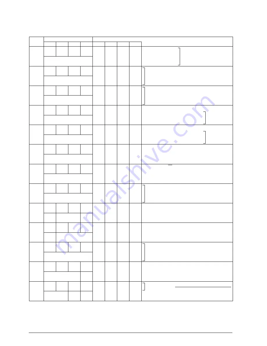
APPENDIX C. E0C6011 I/O MEMORY MAP
40
EPSON
E0C6011 DEVELOPMENT TOOL MANUAL
APPENDIX
C. E0C6011 I/O MEMORY MAP
Address
Comment
D3
D2
Register
D1
D0
Name
Init
∗
1
1
0
073H
K03
K02
K01
K00
R
K03
K02
K01
K00
–
∗
2
–
∗
2
–
∗
2
–
∗
2
High
High
High
High
Low
Low
Low
Low
Input port data (K00–K03)
070H
TM3
TM2
TM1
TM0
R
TM3
TM2
TM1
TM0
0
0
0
0
Clock timer data (2 Hz)
Clock timer data (4 Hz)
Clock timer data (8 Hz)
Clock timer data (16 Hz)
075H
EIK03
EIK02
EIK01
EIK00
R/W
EIK03
EIK02
EIK01
EIK00
0
0
0
0
Enable
Enable
Enable
Enable
Mask
Mask
Mask
Mask
Interrupt mask register (K00–K03)
07EH
TMRST
0
0
IOC0
W
R/W
R
TMRST
0
∗
3
0
∗
3
IOC0
Reset
–
∗
2
–
∗
2
0
Reset
–
–
Output
–
–
–
Input
Clock timer reset
Unused
Unused
I/O control register 0 (P00–P03)
078H
CSDC
EIT2
EIT8
EIT32
R/W
CSDC
EIT2
EIT8
EIT32
0
0
0
0
Static
Enable
Enable
Enable
Dynamic
Mask
Mask
Mask
LCD drive switch
Interrupt mask register (clock timer 2 Hz)
Interrupt mask register (clock timer 8 Hz)
Interrupt mask register (clock timer 32 Hz)
0FFH
CLKFQ1 CLKFQ0
0
LCDON
R
R/W
R/W
CLKFQ1
CLKFQ0
0
∗
3
LCDON
0
0
–
∗
2
1
–
On
–
Off
Peripheral system
clock selection
Unused
LCD display On/Off conrol
079H
0
IT2
IT8
IT32
R
0
∗
3
IT2
∗
4
IT8
∗
4
IT32
∗
4
–
∗
2
0
0
0
–
Yes
Yes
Yes
–
No
No
No
Unused
Interrupt factor flag (clock timer 2 Hz)
Interrupt factor flag (clock timer 8 Hz)
Interrupt factor flag (clock timer 32 Hz)
07AH
0
IK0
0
0
R
0
∗
3
IK0
∗
4
0
∗
3
0
∗
3
–
∗
2
0
–
∗
2
–
∗
2
–
Yes
–
–
–
No
–
–
Unused
Interrupt factor flag (K00–K03)
Unused
Unused
07CH
R03
R02
R01
R00
R/W
R03
R02
R01
R00
0
0
0
0
High
High
High
High
Low
Low
Low
Low
Output port (R03, BZ)
Output port (R02, FOUT)
Output port (R01)
Output port (R00, BZ)
07DH
P03
P02
P01
P00
R/W
P03
P02
P01
P00
–
∗
2
–
∗
2
–
∗
2
–
∗
2
High
High
High
High
Low
Low
Low
Low
I/O port data (P00–P03)
Output latch is reset at initial reset
0FEH
0
0
0
IOC1
R
R/W
0
∗
3
0
∗
3
0
∗
3
IOC1
–
∗
2
–
∗
2
–
∗
2
0
–
–
–
Output
–
–
–
Input
Unused
Unused
Unused
I/O control register 1 (P10–P13)
0FDH
P13
P12
P11
P10
R/W
P13
P12
P11
P10
–
∗
2
–
∗
2
–
∗
2
–
∗
2
High
High
High
High
Low
Low
Low
Low
I/O port data (P10–P13)
Output latch is reset at initial reset
∗
1
∗
2
∗
3
Initial value at initial reset
Not set in the circuit
Always "0" being read
∗
4
∗
5
Reset (0) immediately after being read
f
CLK
is selectable from f
OSC
, f
OSC
/2, f
OSC
/3 and f
OSC
/4 using the CLKFQ1–CLKFQ0 register.
0F6H
BZFQ
0
0
0
R/W
R
BZFQ
0
∗
3
0
∗
3
0
∗
3
0
–
∗
2
–
∗
2
–
∗
2
f
CLK
/32
–
–
–
f
CLK
/16
–
–
–
Buzzer frequency selection
∗
5
Unused
Unused
Unused
00
f
OSC
01
f
OSC
/2
10
f
OSC
/3
11
f
OSC
/4
[CLKFQ1, 0]:
f
CLK
:
When f
CLK
= 65,536 Hz
When f
CLK
= 65,536 Hz
When f
CLK
= 65,536 Hz


