3 FUNCTION OPTION GENERATOR FOG6011
14
EPSON
E0C6011 DEVELOPMENT TOOL MANUAL
11 LCD specification
Table 3.3.1 Common duty selection standard
Number of segments
Common duty
1–76
1/2
77–114
1/3
115–152
1/4
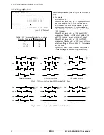
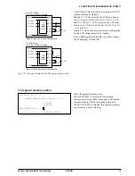
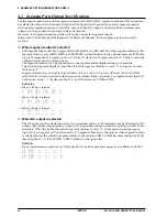
Fig. 3.3.8 Drive waveform from COM terminals (1/2 bias)
Fig. 3.3.7 Drive waveform from COM terminals (1/3 bias)
COM0
COM1
COM2
COM3
1/3 duty drive waveform
1/4 duty drive waveform
V
DD
V
L1
V
L2
V
L3
COM0
COM1
COM2
COM3
V
DD
V
L1
V
L2
V
L3
COM0
COM1
COM2
COM3
1/2 duty drive waveform
V
DD
V
L1
V
L2
V
L3
COM0
COM1
COM2
COM3
1/3 duty drive waveform
1/4 duty drive waveform
V
DD
V
L1
, V
L2
V
L3
COM0
COM1
COM2
COM3
V
DD
V
L1
, V
L2
V
L3
COM0
COM1
COM2
COM3
1/2 duty drive waveform
V
DD
V
L1
, V
L2
V
L3
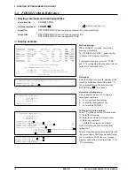
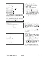
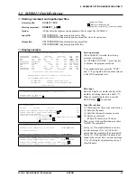
*** OPTION NO.11 ***
--- << LCD COMMON DUTY AND BIAS >> ---
1. 1/4 DUTY,1/2 BIAS
2. 1/3 DUTY,1/2 BIAS
3. 1/2 DUTY,1/2 BIAS
PLEASE SELECT NO.(1) ? 1
1. 1/4 DUTY,1/2 BIAS SELECTE
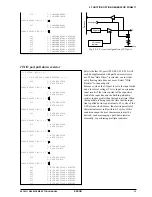
Select the specification (drive duty) for the LCD drive
circuit.
•
Drive duty
Select a drive duty.
When 1/2 duty is selected, up to 76 segments of LCD
panel can be driven with 2 COM terminals and 38
SEG terminals. When 1/3 duty is selected, up to 114
segments can be driven with 3 COM terminals, and
when 1/4 duty is selected, up to 152 segments with 4
COM terminals.
When 1/2 duty is selected, the COM0 and COM1
terminals are effective for COM output and the COM2
and COM3 terminals always output an off signal.
When 1/3 duty is selected, the COM0 to COM2
terminals are effective and the COM3 terminal always
outputs an off signal. Refer to Table 3.3.1 for common
duty selection.
Figures 3.3.7 and 3.3.8 show the drive waveforms of
1/3 bias driving and 1/2 bias driving, respectively.
(for 3-V LCD model)


