


EPSON Stylus CX4100/CX4200/CX4700/CX4800/DX4200/DX4800/DX4850
Revision A
ADJUSTMENT
Adjustment Except Adjustment Program
180
5.3 Adjustment Except Adjustment Program
Following is adjustment except Adjustment Program.
5.3.1 PG Adjustment
Parts to be Removed and Replaced
Removal and Replacement of Carriage Unit
Removal and Replacement of Print Head
Adjustment procedure
1. Make sure that the printer is turned off.
2. Set the ink cartridges into the Carriage Unit
3. Prepare the thickness gauge. (The thickness should be 1.45mm.)
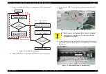
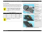
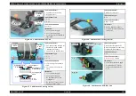
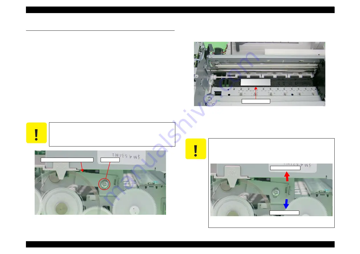
4. Loosen the screw (C.B.S 3x6) for securing the Parallel Adjustment Lever
(Left).
Figure 5-6. Parallel Adjustment Lever (Left) Location
5. Release the Carriage Lock if the Carriage Unit is locked.
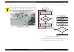
6. Set the thickness gauge at the position shown by the figure. The thickness
gauge should be placed between the front of the Paper Guide Front Unit and
the center ribs.
Figure 5-7. Placement position for thickness gauge
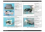
7. Confirm that PG Lever is lowered. If PG Lever is raised, lower it.
8. Move the Carriage Unit on the thickness gauge by using the Timing Belt, and
check whether the thickness gauge moves or not.
C A U T I O N
Do not remove a screw completely. (two or three revolution)
You need not to loosen the screw securing the Parallel
Adjustment Lever (Right).
C.B.S 3x6
Parallel Adjustment Lever (Left)
C A U T I O N
If you push the Carriage Unit directly, it’s possible to damage
the Print Head surface by the friction with the thickness gauge.
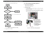
Following is the relationship between “Parallel Adjustment
Lever (Left) operation” and “Platen gap reaction”.
Figure 5-8. Relationship between Parallel Adjustment Lever (Left)
Operation & Platen Gap
Thickness gauge
PG up (narrower)
PG down (wider)
Summary of Contents for CX4200 - Stylus Color Inkjet
Page 9: ...C H A P T E R 1 PRODUCTDESCRIPTION ...
Page 60: ...C H A P T E R 2 OPERATINGPRINCIPLES ...
Page 87: ...C H A P T E R 3 TROUBLESHOOTING ...
Page 121: ...C H A P T E R 4 DISASSEMBLY ASSEMBLY ...
Page 171: ...C H A P T E R 5 ADJUSTMENT ...
Page 187: ...C H A P T E R 6 MAINTENANCE ...
Page 194: ...C H A P T E R 7 APPENDIX ...
Page 221: ...Model PX A650 Stylus CX4700 CX4800 DX4800 DX4850 Board C571 PNL Rev D Sheet 1 1 ...
Page 222: ...Model Stylus CX4100 CX4200 DX4200 Board C577 PNL Rev A Sheet 1 1 ...


