


EPSON Stylus CX4100/CX4200/CX4700/CX4800/DX4200/DX4800/DX4850
Revision A
DISASSEMBLY/ASSEMBLY
Scanner Section
166
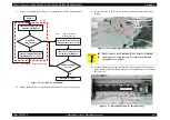
4.5.3 Scanner Motor Unit/Scanner HP Sensor/
Driven Pulley
External view
Figure 4-53. Removing Scanner Motor Unit/Scanner HP Sensor/Driven Holder
Part/Unit that should be removed before removing Scanner Motor Unit/
Scanner HP Sensor/Driven Holder
Document Cover / Scanner Unit / Scanner Housing, Upper
Removal procedure
1.
Move the Scanner Carriage Unit to the center of the Scanner Unit.
2.
Push the Driven Holder to the direction of the arrow, and remove Compound
Gears 22.8, 7.762, Driven Holder, and Scanner Timing Belt.
3.
Release the shaft of the hinge L from the bearing of the Scanner Housing,
Lower.
4.
Disconnect the Scanner Connector Cable and the Scanner HP Sensor
Connector Cable from the tab of the hinge L, and pull them out from the notch
of the Scanner Housing, Lower.
5.
Remove the screw (x1,
) that secures the Scanner HP Sensor, and remove
the Scanner HP Sensor.
6.
Release the Scanner Motor Connector Cable and the Scanner HP Sensor
Connector Cable from the tab of the Scanner Housing, Lower.
7.
Remove the screws (x2,
) that secure the Scanner Motor Unit, and remove
the Scanner Motor Unit.
1
3
Driven Holder
Compound Gears
22.8, 7.762
2
Scanner Timing Belt
Hinge L
Scanner Motor Connector Cable
Notch
Scanner HP Sensor
Connector Cable
C.B.P 3x8 F/Zn (5±1kgfcm)
É_É{
Scanner HP
Sensor
C.B.P. 3x8 F/Zn (5±1kgfcm)
Guide Pin
Tab
Shaft
Scanner
Motor Unit
C.B.P. 3x8 F/Zn (5±1kgfcm)
Guide Pins
Rib
Driven Holder Spring
When installing the Scanner Motor Unit, match the guide pins
(x2,
) of the Scanner Housing, Lower with the positioning holes
(x2) of the Scanner Motor Unit.
When installing the Scanner HP Sensor, match the guide pin (x1)
of the Scanner Housing, Lower with the positioning hole (x1,
)
of the Scanner HP Sensor.
Route the Scanner Motor Connector Cable and the Scanner HP
Sensor Connector Cable as shown in the figure.
Insert the Driven Holder Spring into the rib of the Driven
Holder.
Summary of Contents for CX4200 - Stylus Color Inkjet
Page 9: ...C H A P T E R 1 PRODUCTDESCRIPTION ...
Page 60: ...C H A P T E R 2 OPERATINGPRINCIPLES ...
Page 87: ...C H A P T E R 3 TROUBLESHOOTING ...
Page 121: ...C H A P T E R 4 DISASSEMBLY ASSEMBLY ...
Page 171: ...C H A P T E R 5 ADJUSTMENT ...
Page 187: ...C H A P T E R 6 MAINTENANCE ...
Page 194: ...C H A P T E R 7 APPENDIX ...
Page 221: ...Model PX A650 Stylus CX4700 CX4800 DX4800 DX4850 Board C571 PNL Rev D Sheet 1 1 ...
Page 222: ...Model Stylus CX4100 CX4200 DX4200 Board C577 PNL Rev A Sheet 1 1 ...


