EPSON AcuLaser C4000/C4100/C3000
Revision F
Troubleshooting
Level 2 FIP
3-114
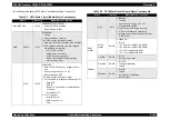
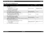
Wrong Photoconductor
Description
The appropriate Photoconductor Unit is not installed.
LED
The Ready LED is off and the Error LED is on.
Treatment
By opening the Cover A and D to install the appropriate Photoconductor Unit
and closing the covers, the error is automatically released.
Reference FIP
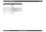
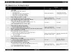
uuuu Toner Out
Description
The printer detects that a toner is empty according to the Toner End sensor
and the toner's Dispense Time of each color of the engine, and printing stops.
Printing in the Toner End status cannot provide proper color expression,
therefore the error cannot be released by pressing the Start/Stop button. The
uuuu shows CMYK corresponding to the each C, M, Y, K toner cartridge,
indicating only the toner cartridge detected that it contains no remaining toner.
LED
The Ready LED is off and the Error LED is on.
Treatment
Replace toner Cartridge.
Reference FIP
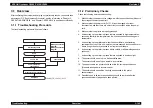
Replace Photocondctr
Description
Printing stops since this error cause damages to the engine.
NOTE:
Do not open to an user this.
PHD Life Over2 of the engine status STSLIFE2 is activated.
LED
The Ready LED is off and the Error LED is on.
Treatment
Open the Cover A, and then open the Cover D. Replace the Photoconductor
Unit with a new one. Closing the Cover D and A automatically releases the
error.
Reference FIP
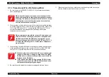
Replace TransferUnit
Description
The Transfer Unit's life cycle has ended.
NOTE:
Do not open to an user this.
Since the number of printed copies or Dispense Time after turning the Waste
Toner sensor of the engine on has reached to the setting value, the printer
detects that the life cycle of the Transfer Unit ends, and then printing stops.
LED
The Ready LED is off and the Error LED is on.
Treatment
By opening the Cover A, replacing the used Transfer Unit with a new Transfer
Unit, and closing the Cover A, the error is automatically released.
Reference FIP
Summary of Contents for AcuLaser C3000 Series
Page 20: ...C H A P T E R 1 PRODUCTDESCRIPTIONS ...
Page 71: ...C H A P T E R 2 OPERATINGPRINCIPLES ...
Page 118: ...C H A P T E R 3 TROUBLESHOOTING ...
Page 318: ...C H A P T E R 4 DISASSEMBLYANDASSEMBLY ...
Page 472: ...C H A P T E R 5 ADJUSTMENT ...
Page 477: ...C H A P T E R 6 MAINTENANCE ...
Page 491: ...C H A P T E R 7 AcuLaserC4100 ...
Page 548: ......
Page 549: ......
Page 550: ......
Page 551: ......
Page 552: ......
Page 553: ......
Page 554: ......
Page 555: ...C H A P T E R 8 AcuLaserC3000 ...
Page 579: ...Model AcuLaser C3000 Board C569MAIN BOARD Sheet 1 of 5 Rev B ...
Page 580: ...Model AcuLaser C3000 Board C569MAIN BOARD Sheet 2 of 5 Rev B ...
Page 581: ...Model AcuLaser C3000 Board C569MAIN BOARD Sheet 3 of 5 Rev B ...
Page 582: ...Model AcuLaser C3000 Board C569MAIN BOARD Sheet 4 of 5 Rev B ...
Page 583: ...Model AcuLaser C3000 Board C569MAIN BOARD Sheet 5 of 5 Rev B ...
Page 584: ...C H A P T E R 9 APPENDIX ...
Page 674: ......
Page 675: ......
Page 676: ......
Page 677: ......
Page 678: ......
Page 679: ......
Page 680: ......

