


DISASSEMBLY, ASSEMBLY, AND ADJUSTMENT
REV.-A
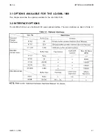
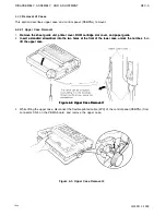
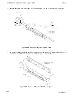
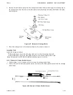
4.2.4 Removal of Printer Mechanism
This section describes the removal of the platen unit, paper guide, and printer mechanism. Before removing
the printer mechanism, take off the platen unit and the paper guide so that the printer mechanism can be removed
quickly and easily.
Figure 4-8. Printer Mechanism Removal
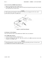
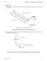
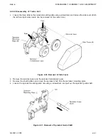
4.2.4.1 Removal of Platen Unit and Paper Guide
1.
Remove the upper case (refer to Section 4.2.1.1).
2.
Turn the shaft holders at the left and right sides of the platen unit as shown in Figure 4-9, and lift the platen
unit to remove it.
a. Push the shaft holder outward using a screwdriver.
b. Turn the shaft holder counterclockwise.
Figure 4-9. Platen Unit Removal
4-8
LQ-500/ L-1000
Summary of Contents for ActionPrinter L-1000
Page 1: ...LQ 500 L 1000 TECHNICAL MANUAL EPSON ...
Page 3: ...REV A REVISION SHEET iv LQ 500 L 1000 ...
Page 18: ...GENERAL DESCRIPTION REV A Figure 1 5 Character Matrix 1 10 LQ 500 L 1000 ...
Page 39: ...PRINCIPLES OF OPERATION REV A 2 2 LQ 500 L 1000 Figure 2 1 Cable Connections ...
Page 44: ......
Page 47: ...PRINCIPLES OF OPERATION REV A Table 2 2 Power Supply Applications 2 10 LQ 500 L 1000 ...
Page 77: ...PRINCIPLES OF OPERATION 2 40 REV A Figure 2 40 Schmitt Trigger Circuit LQ 500 L 1000 ...
Page 100: ...REV A PRINCIPLES OF OPERATION Table 2 20 Control Commands LQ 500 L 1000 2 63 ...
Page 106: ...REV A PRINCIPLES OF OPERATION Figure 2 64 Printing Routine LQ 500 L 1000 2 69 ...
Page 141: ...DISASSEMBLY ASSEMBLY AND ADJUSTMENT Table 4 5 VR2 Specifications REV A 4 26 LQ 500 L 1000 ...
Page 148: ...TROUBLESHOOTING REV A 1 Printer Does Not Operate with Power Switch ON 5 4 LQ 500 L 1000 ...
Page 149: ...REV A TROUBLESHOOTING 2 Abnormal Operation of Carriage LQ 500 L 1000 5 5 ...
Page 151: ...REV A TROUBLESHOOTING Figure 5 3 Printhead Resistance LQ 500 L 1000 5 7 ...
Page 152: ...TROUBLESHOOTING REV A 4 Abnormal Paper Feed with normal printing 5 8 LQ 500 L 1000 ...
Page 153: ...REV A TROUBLESHOOTING 5 Abnormal Operation of Control Panel LQ 500 L 1000 5 9 ...
Page 156: ...TROUBLESHOOTING REV A Table 5 6 Power Supply Circuit Unit Repair 5 12 LQ 500 L 1000 ...
Page 157: ...REV A T R O U B L E S H O O T I N G ...
Page 162: ...REV A MAINTENANCE Figure 6 2 LQ 500 L 1000 Lubrication Points LQ 500 L 1000 6 3 ...
Page 163: ......
Page 168: ......
Page 170: ...REV A APPENDIX Table A 5 µPD7810 7811 Port Functions LQ 500 L 1000 A 5 ...
Page 173: ...APPENDIX REV A Figure A 7 E01A05KA Block Diagram A 8 LQ 500 L 1000 ...
Page 174: ...REV A Table A 6 E01A05KA Pin Functions APPENDIX LQ 500 L 1000 A 9 ...
Page 185: ...APPENDIX REV A A 20 LQ 500 L 1000 ...
Page 186: ...REV A Table A 8 CN2 Connector Table A 9 CN3 Connector Cont A P P E N D I X LQ 500 L 1000 A 21 ...
Page 187: ...APPENDIX REV A Table A 10 CN4 Connector Cont Table A 12 CN6 Connector Cont A 22 LQ 500 L 1000 ...
Page 188: ...REV A APPENDIX Table A 17 Part No Reference Table LQ 500 L 1000 ...
Page 189: ...APPENDIX REV A Figure A 24 LQ 500 Exploded Diagram A 24 LQ 500 L 1000 ...
Page 190: ...REV A APPENDIX Figure A 25 M5410 Printer Mechanism Exploded Diagram LQ 500 L 1000 A 25 ...
Page 191: ...APPENDIX REV A Figure A 26 Tractor Unit A 26 LQ 500 L 1000 ...
Page 192: ......


