EPSON Stylus PHOTO 2100/2200
Revision B
ADJUSTMENT
Adjustments
204
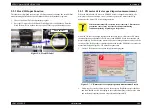
5.2.5 Head Angular Adjustment
This adjustment is made to correct physically the assembling error of the Printhead
relative to the CR unit. To make Head angular adjustment, adjust the angle of the Head
relative to the CR main operation direction by moving the adjust lever installed on the
right side face of the CR unit. By shifting the Y nozzle line with respect to the Head Bk
nozzle line with this Adjust lever in the paper loading direction, make adjustment until
the Head does not tilt.
Before starting this adjustment, remove the following part.
!
Upper housing
1.
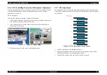
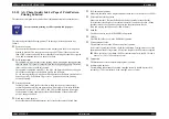
Start the adjustment program and select Head angular adjustment from the
adjustment menu. Click the Print button to print the head angular adjustment
pattern.
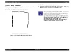
2.
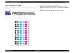
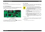
In the printed Head tilt adjustment pattern, make adjustment until each light
magenta rule is aligned with the center of the black rules.
Figure 5-15. Head Angular Adjustment Pattern
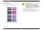
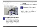
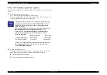
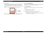
The following figure shows the relationships between the Adjust lever and Head
adjustment check pattern.
Figure 5-16. Adjust Lever and Head Angular Adjustment Check Pattern
C H E C K
P O I N T
"
Use Photo quality ink jet paper for Head angular adjustment.
Black
Light magenta
Adjustment unnecessary
Target position
The light magenta lines move
upward to the target position.
The light magenta lines move
downward to the target position.
Adjust lever
Adjustment necessary
Summary of Contents for 2200 - Stylus Photo Color Inkjet Printer
Page 1: ...EPSONStylusPHOTO2100 2200 Color Inkjet Printer SEIJ01 016 SERVICE MANUAL ...
Page 8: ...C H A P T E R 1 PRODUCTIONDESCRIPTION ...
Page 39: ...C H A P T E R 2 OPERATINGPRINCIPLES ...
Page 69: ...C H A P T E R 3 TROUBLESHOOTING ...
Page 115: ...C H A P T E R 4 DISASSEMBLYANDASSEMBLY ...
Page 187: ...C H A P T E R 5 ADJUSTMENT ...
Page 214: ...C H A P T E R 6 MAINTENANCE ...
Page 226: ...C H A P T E R 7 APPENDIX ...
Page 254: ......
Page 255: ......
Page 256: ......
Page 257: ......
Page 258: ......


