EPS Stromversorgung PS 5040-10 A Operating Manual Download Page 28

Page 28

EPS Stromversorgung GmbH

Alter Postweg 101 • 86159 Augsburg

Germany

Fon: +49 821 / 570451-0

Fax: +49 821 / 570451-25

www.eps-germany.de

[email protected]

PS 5000 A Series

3.4 

Manual operation

3.4.1  Switching the device on

The device should, as far as possible, always be switched on using the toggle switch on the front of the device. 

Alternatively this can take place using an external cutout (contactor, circuit breaker) of suitable current capacity.
After switching on and a certain start-up time, the device will be ready for use. It also restores the last condition of 

the DC output like it was when switching the device off the last time, so either on or off. All set values are always 

saved and restored. 

3.4.2  Switching the device off

On switch-off the last output condition and the most recent set values are saved. The DC output is immediately 

switched off and a power fail error PF (only 640 W models) will be indicated, but can be ignored here, and after a 

short while the device will be completely powered off.

3.4.3  Manual adjustment of set values

Adjusting the set values of voltage, current and power is the fundamental 

operating possibility of a power supply and hence the two rotary knobs on 

the front of the device are usually assigned to voltage (left-hand knob) and 

current (right-hand knob).
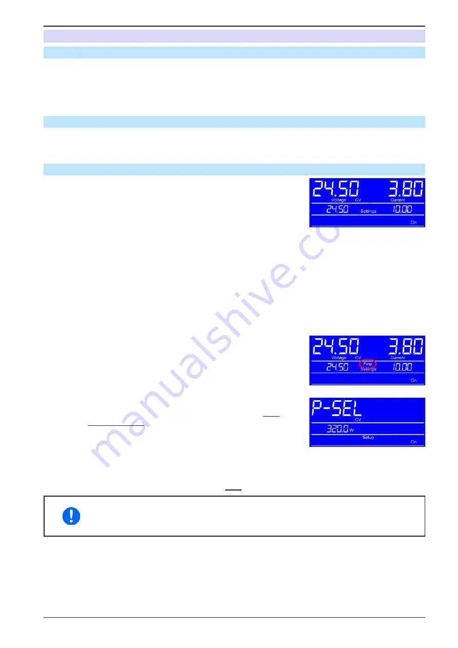
The manual adjustment of the set values can only be done while the device is 

not in a different mode, like adjustment mode for OVP/OCP values. See figure 

to the right. In normal operation mode, the middle row shows the set values.
The power set value is not directly adjustable from here.
The control panel lock (see 

3.4.7

) can block the user from adjusting set values.


How to adjust voltage and current manually

1. 

In normal operation (see example screenshot above), rotate the left-hand knob to adjust voltage and the 

right -hand knob to adjust current, no matter if the DC output is switched on or off.

2. 

While adjusting values, you can push any of the knobs to switch between fine and coarse adjustment of 

values. See below.


► How to switch between fine and coarse value adjustment

1. 

Coarse adjustment mode is default after the unit has been powered. It 

will increment or decrement a value by 1. You can switch to fine adjust

-

ment mode anytime by shortly pushing any of the rotary knobs. This 

mode is indicated in the displays as shown in the example screenshot 

to the right.


How to adjust power manually

1. 

In normal operation (see example screenshot above), push 

both

 rotary 

knobs 

simultaneously

2. 

The display should switch to setup mode, in this case for power value 

adjustment. See example screenshot to the right.

3. 

Adjust the indicated power value (unit W) with the left-hand rotary knob, like when adjusting voltage. Switch-

ing between fine and coarse adjustment as described above. In case the DC output is switched on, the 

adjusted values immediately becomes effective.

4. 

Leave the power adjustment mode by pushing 

both

 rotary buttons again and simultaneously.

Adjusting set value always submits the value to the power stage immediately, no matter if the 

DC output is switched on or off.

The set values of voltage and current are part of the recall sets (see 3.4.6), the power set value 

is not.

Summary of Contents for PS 5040-10 A

Page 1: ...E P S S t r o m v e r s o r g u n g Doc ID PS5EN Revision 05 Date 01 2017 Operating Guide PS 5000 A DC Laboratory Power Supply...

Page 2: ......

Page 3: ...nection of remote sensing 23 2 3 7 Connecting the USB port rear side 24 2 3 8 Initial commission 25 2 3 9 Commission after a firmware update or a long period of non use 25 3 OPERATIONANDAPPLICATION 3...

Page 4: ...ety notices as well as general notices in this document are shown in a box with a symbol as follows Symbol for a life threatening danger Symbol for general safety notices instructions and damage prote...

Page 5: ...current of the device in Ampere Maximum voltage of the device in Volt Series 5 Series 5000 Type identification PS Power Supply usually programmable PSI Power Supply Intelligent always programmable ELR...

Page 6: ...ccur which can cause burns as well as damage to the equipment and to the user For electronic loads do not connect power sources to equipment under power sparking may occur which can cause burns as wel...

Page 7: ...responsibilities for operation maintenance and cleaning of the equipment ensure that all employees who use the equipment have read and understood the manual Furthermore the users are to be regularly s...

Page 8: ...or the load could be damaged Signal OCP OverCurrent Shutdown of the DC output due to excess of the preset limit Non critical protects the load from excessive current consumption Signal OPP OverPower...

Page 9: ...0 2 UNom 0 2 UNom 0 2 UNom Ripple 2 40 mVPP 5 mVRMS 80 mVPP 10 mVRMS 150 mVPP 30 mVRMS Remote sensing compensation Max 6 UNom Max 6 UNom Max 6 UNom Current regulation Adjustment range 0 10 2 A 0 5 1 A...

Page 10: ...inlet rear exhaust Ambient temperature 0 50 C Storage temperature 20 70 C Humidity 80 not condensing Standards EN 61010 EN 61326 Overvoltage category 2 Protection class 1 Pollution degree 2 Operation...

Page 11: ...UNom 0 2 UNom Ripple 2 40 mVPP 5 mVRMS 80 mVPP 10 mVRMS 150 mVPP 30 mVRMS Remote sensing compensation Max 6 UNom Max 6 UNom Max 6 UNom Current regulation Adjustment range 0 20 4 A 0 10 2 A 0 4 08 A A...

Page 12: ...inlet rear exhaust Ambient temperature 0 50 C Storage temperature 20 70 C Humidity 80 not condensing Standards EN 61010 EN 61326 Overvoltage category 2 Protection class 1 Pollution degree 2 Operation...

Page 13: ...lay Accuracy 4 0 2 UNom 0 2 UNom 0 2 UNom Ripple 2 40 mVPP 5 mVRMS 80 mVPP 10 mVRMS 150 mVPP 30 mVRMS Remote sensing compensation Max 6 UNom Max 6 UNom Max 6 UNom Current regulation Adjustment range 0...

Page 14: ...let rear exhaust Ambient temperature 0 50 C Storage temperature 20 70 C Humidity 80 not condensing Standards EN 61010 EN 61326 Overvoltage category 2 Protection class 1 Pollution degree 2 Operational...

Page 15: ...any Fon 49 821 570451 0 Fax 49 821 570451 25 www eps germany de info eps germany de PS 5000 A Series Figure 1 Front side Figure 2 Back side 1 8 4 Views A Mains switch B Control panel C DC output D Exh...

Page 16: ...bH Alter Postweg 101 86159Augsburg Germany Fon 49 821 570451 0 Fax 49 821 570451 25 www eps germany de info eps germany de PS 5000 A Series Figure 3 Right hand side view 640 W model Figure 4 Right han...

Page 17: ...Button OVP OCP Switches to adjustment of OVP OCP and OPP values Button Local Activation deactivation of the remote control inhibit see 3 5 2 Button Lock Activation deactivation of the control panel l...

Page 18: ...ut Series or parallel connection are possible The DC output clamps on the front are suitable to connect soldered cable ends spade lugs cable end sleeves or 4mm B schel plugs All models are controlled...

Page 19: ...ssigned either to the output voltage and related parameter OVP or the power and the related parameter OPP whereas the right hand rotary knobs is always assigned to the output current and related param...

Page 20: ...00 V 4 0 1 V 10 A 20 A 4 0 01 A 320 W 4 0 1 W 40 A 4 0 01 A 640 W 4 0 1 W In manual operation every set value can be set in the increments given above In this case the actual output values set by the...

Page 21: ...note and or parts list see section 1 9 2 Scope of delivery An obviously damaged device e g loose parts inside damage outside must under no circumstances be put in operation 2 3 Installation 2 3 1 Prep...

Page 22: ...auxiliary outputs and then connecting the load on one of the main outputs on the front unless the total current does not exceed 32 A With the 40 A model it is not allowed to use and plug 4mm B schel p...

Page 23: ...6 Connection of remote sensing In order to compensate to a certain degree the voltage loss in a DC cable the device provides the possibility to connect the remote sensing input Sense to the load The...

Page 24: ...C device and is usually integrated in current operating systems such as Windows 7 or 10 But it is strongly recommended to use and install the included driver installer on USB stick to gain maximum com...

Page 25: ...settings for set values safety and monitoring functions and communication are suitable for your application and change them where necessary as described in the manual In case of remote control via PC...

Page 26: ...2 Current regulation constant current current limiting Current regulation is also known as current limitation or constant current mode CC The DC output current is held constant by the power supply onc...

Page 27: ...switch off the DC output and can occur if the power supply itself as a voltage source generates an output voltage higher than set for the overvoltage alarm limit OVP 0 110 UNom or the connected load s...

Page 28: ...ode the middle row shows the set values The power set value is not directly adjustable from here The control panel lock see 3 4 7 can block the user from adjusting set values How to adjust voltage and...

Page 29: ...ing it vice versa means first to push both knobs and then pushbutton OVP OCP 2 The display switches to show the OPP threshold unit W as indicated in the example screenshot to the right 3 Adjust the va...

Page 30: ...the former values won t be overwritten After using any of these two buttons recall mode is left After the desired number of presets have been defined to custom needs they can be recalled and used How...

Page 31: ...bited condition the status Local will be displayed lower row of the display See example screenshot to the right Activating the inhibit can be useful if the device is remotely controlled by software or...

Page 32: ...caused by the device being faulty or by an external source The DC output will be switched off 0 V 1 1 UNom OCP OverCurrent Protection Triggers an alarm if the DC output current reaches the defined thr...

Page 33: ...pole of any unit in the series connection must have a potential of 200 V against ground PE Remote sensing must not be wired to the load only the sense bridges on the aux output rear are allowed Serie...

Page 34: ...n is abroad the necessary customs papers are attached 4 2 1 Replacing a defect mains fuse The device is protected by one 5x20 mm fuse T16 A 250 V which is located on the rear of the device inside a fu...

Page 35: ......

Page 36: ......

Reviews: