http://www.GuitarAmplifierPCBs.com
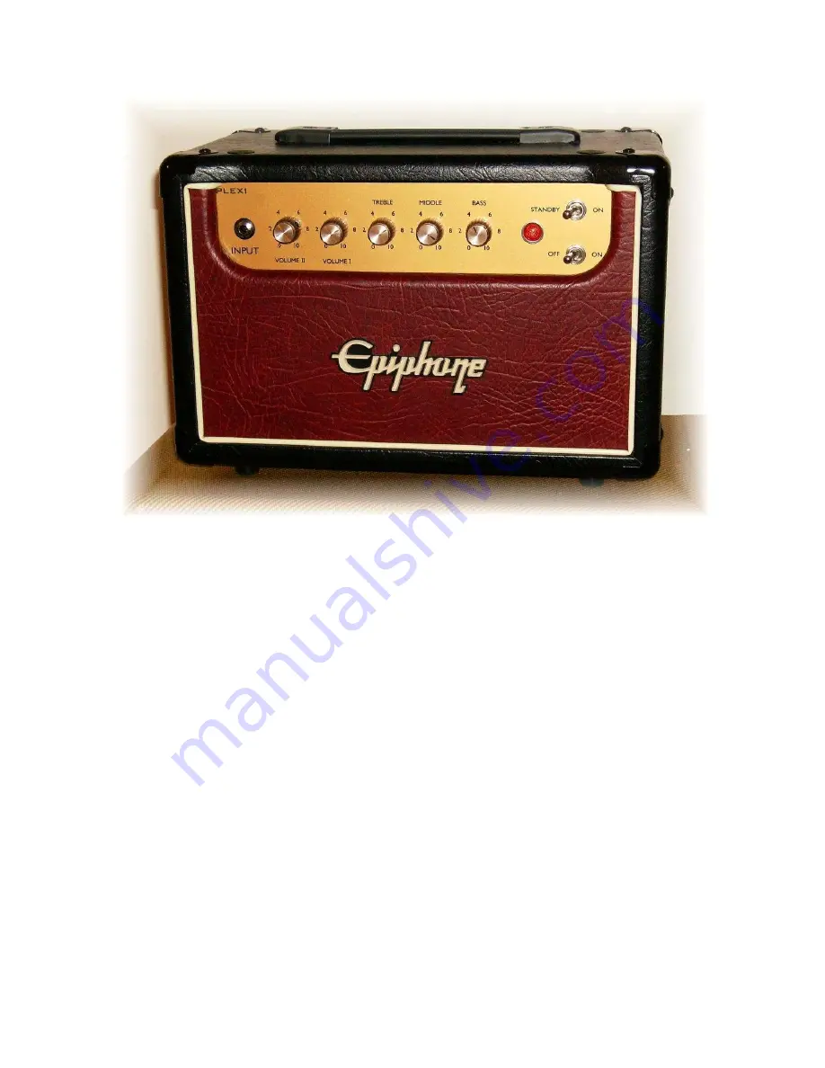
Plexi SE PCB Valve Junior Conversion
Version 2
Build Manual
23 August 2009
1 of 34
Plexi SE PCB
Valve Junior Conversion
Page 1: ...http www GuitarAmplifierPCBs com Plexi SE PCB Valve Junior Conversion Version 2 Build Manual 23 August 2009 1 of 34 Plexi SE PCB Valve Junior Conversion Build Manual...
Page 2: ...PCB package This manual provides instruction for the assembly of version 1 0 of the Plexi SE PCB To simplify things The Epiphone Valve Junior will be referred to as EVJ and This manual guides you thro...
Page 3: ...w the basic safety practices Building modifying or repairing tube amplifiers should only be performed by trained personnel 3 Disclaimer of Liability GuitarAmplifierPCBs com assumes no liability or res...
Page 4: ...out and Drill 11 6 1 1 Layout the Plexi SE PCB for Drilling 11 6 1 2 Layout the Faceplate for drilling 12 6 1 3 Drilling the Chassis 13 7 Plexi SE PCB 13 7 1 Assemble the Plexi SE PCB 13 7 1 1 PCB Sta...
Page 5: ...it doesn t require expensive tools or complex equipment 4 1 Here s what you ll need 4 1 1 Parts The Plexi SE PCB Misc parts and components refer to the Plexi SE PCB parts list document for a full lis...
Page 6: ...Take off the back panel by removing the seven 7 screws using a Phillips head screw driver Be careful pulling off the back panel They are typically stuck onto the chassis Slowly pull from each side to...
Page 7: ...e spring lifts the shield off the per amp tube pull the tubes out and unclip the power tube retainer These items can be discarded They will not be used later in the build Now that the tubes and their...
Page 8: ...ead posts on the stock circuit board for storage We are going to clean up the inside of the chassis by pulling any unused power transformer leads outside of the chassis cavity Disconnect these three 3...
Page 9: ...chassis Leave it connected to the stock EVJ circuit board The volume pot will be glued to the chassis This part will NOT be used later in the build so use whatever force you need 5 2 5 Remove the Stoc...
Page 10: ...ld Manual 23 August 2009 10 of 34 Remove the stock circuit board and pull all of the power transformer leads to the rim of the chassis Salvage the ground wire from the stock circuit board for use late...
Page 11: ...ing in the chassis 6 1 1 Layout the Plexi SE PCB for Drilling Since the Plexi SE PCB was designed to use the stock EVJ chassis standoffs the best method to mark the additional chassis holes is to inst...
Page 12: ...on GuitarAmplifierPCBs com If you can not print onto 11x17 paper you can take an electronic version of the drill plan to Kinkos They will print it professionally for under 1 Print out a copy of the VJ...
Page 13: ...Finally the assembly of the Plexi SE PCB begins Did you check you make sure you have all of the parts you ll need to complete the assembly I wish I did The graphics used in the assembly of this circui...
Page 14: ...of the board 7 1 2 Tube Sockets The tube sockets get installed on the back side of the board too Insert the tube sockets as shown The noval 9 pin sockets only go in one way on the back side However t...
Page 15: ...in arching between the spade connectors and the ground plane This may result in charring of the circuit board poor amplifier performance transformer damage and may pose a safety and or fire hazard Aga...
Page 16: ...23 August 2009 16 of 34 7 1 4 Diodes Install the four 4 rectifier diodes Orient the diodes as indicated on the circuit board Bend the leads over insert them into the board and bend them to the side a...
Page 17: ...SE PCB to have a 1959 Super Lead Plexi preamp install the various components as shown in the picture below Determine the component value from the schematic and or chassis layout drawing Notice how th...
Page 18: ...xi SE PCB to have a Cascade or JCM800 preamp install the various components as shown in the picture below Determine the component value from the schematic and or chassis layout drawing Notice how the...
Page 19: ...mplifierPCBs com Plexi SE PCB Valve Junior Conversion Version 2 Build Manual 23 August 2009 19 of 34 7 1 7 Wiring the Heaters Cut two 12 lengths of wire and twist them together as shown Cut this twist...
Page 20: ...e Junior Conversion Version 2 Build Manual 23 August 2009 20 of 34 Twist the wires together as shown Strip of the insulation off of the ends of the wires Insert the leads into the solder pad locations...
Page 21: ...solder in place Here s what the heater wiring should look like when properly installed 7 1 8 Filter Capacitors Insert the five 5 filter capacitors in their locations as indicated on the board These ca...
Page 22: ...rs as shown These capacitors are polarized Be careful to install them by inserting the positive lead the longer one into the square pad and the negative lead as indicated by the downward arrow and sym...
Page 23: ...m all of the remaining components in the circuit Refer to the latest version of the schematic or chassis layout drawing on GuitarAmplifierPCBs com the Plexi SE PCB and or the component package to iden...
Page 24: ...for one input jack Prepare the stock input jack by cutting off the stock connector Cut off the connector that plugged into the stock EVJ circuit board Leave the input connector plugged into the input...
Page 25: ...l potentiometers and ground lug Here s where all of the lead connections are You should install the ground wire now I highly recommend that you clean the solder flux residue from all of the solder joi...
Page 26: ...of seven 7 inches Strip the ends of the wires clean and install them in the locations marked above Twist the three VR1 Volume I wires together Twist the three VR2 Volume II wires together The color o...
Page 27: ...it board to their respective solder posts on the control potentiometers Trim the wires to length strip the insulation from the ends and solder the wires in to place on the control pots Refer to the sc...
Page 28: ...its respective solder pad location Do not insert the wire lead too far into the board The wire may make contact the metal chassis underneath Solder each wire lead to the board Here s a representation...
Page 29: ...performed and completed properly Look for the following Missing components Damaged components or leads Solder joints that may have spilled over onto a nearby component or solder pad Loose connections...
Page 30: ...the speaker impedance with the appropriate output jack Failure to connect a speaker will cause harm and eventual failure of the output transformer Verify the amp s power switch is in the Off position...
Page 31: ...August 2009 31 of 34 The unloaded B voltage should measure the same all the way up the power rail A slight fluctuation is normal If a difference greater than 5 10 Vdc is measured something is drawing...
Page 32: ...connector Secure the black ground lead of your voltmeter to the chassis star ground lug Plug the amplifier into a speaker cabinet Match the speaker impedance with the appropriate output jack Failure t...
Page 33: ...http www GuitarAmplifierPCBs com Plexi SE PCB Valve Junior Conversion Version 2 Build Manual 23 August 2009 33 of 34...
Page 34: ...he chassis back into the stock cabinet Fasten the chassis to the cabinet with the stock screws Insert the screw caps into the sockets Press them in until they are flush with the cabinet surface Attach...