Zori Monitor Lift Installation Guide – Rev A.
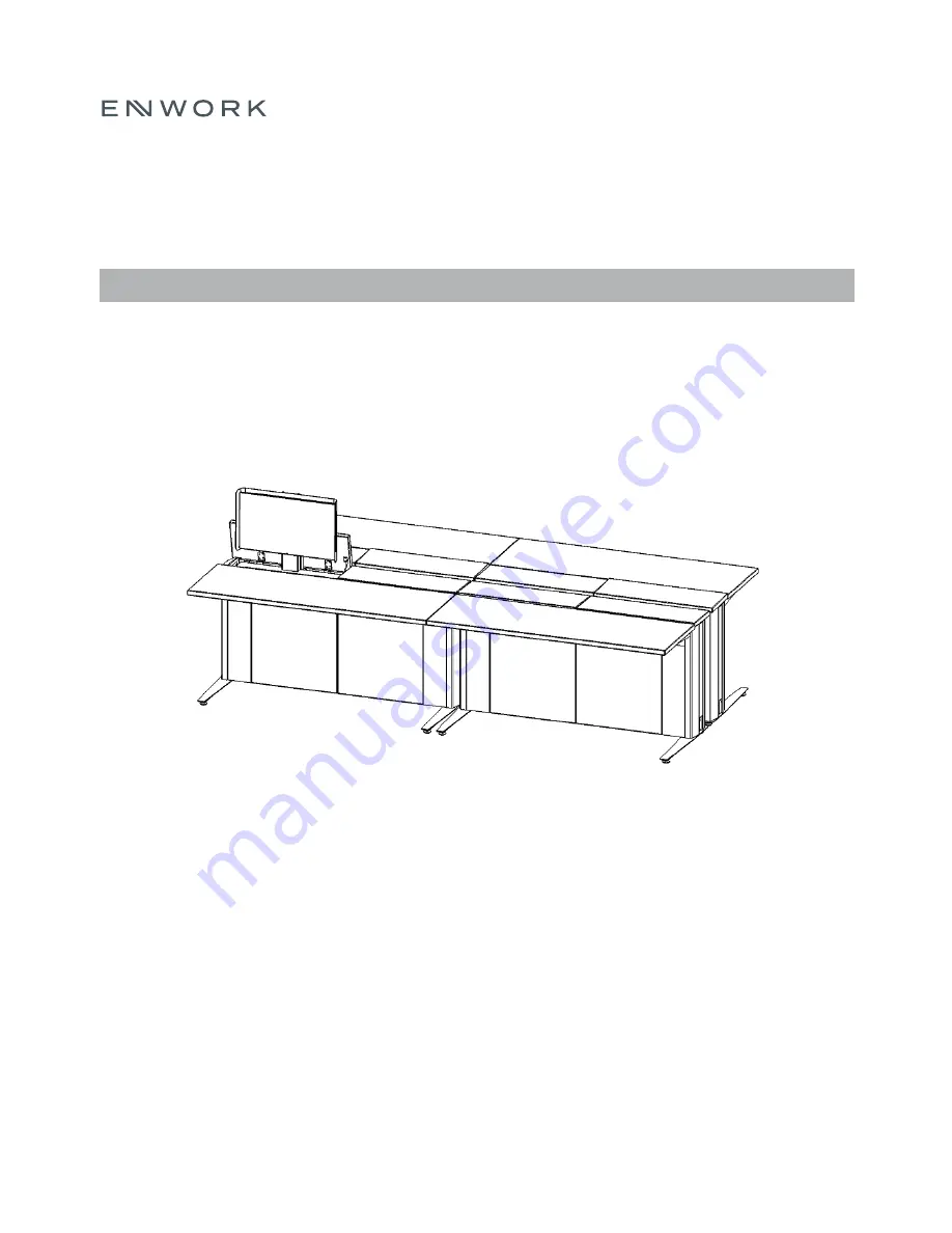
Z O R I M O N I T O R L I F T
I N S T A L L A T I O N I N S T R U C T I O N S
M O N I T O R L I F T
Z I 0 0 1 3
Page 1: ...Zori Monitor Lift Installation Guide Rev A Z O R I M O N I T O R L I F T I N S T A L L A T I O N I N S T R U C T I O N S M O N I T O R L I F T Z I 0 0 1 3 ...
Page 2: ... in the desired configuration near its designated power source before starting Utilize the cutout in the end panels to lift the tables if needed To open doors unlock and pull lightly Doors will open slightly Lift up to remove P R E I N S T A L L T I P S ...
Page 3: ...onitor Lift Table CYPxxxxxxx Top Filler Panel End 2x CYL 1888 xE Panel Clip 2x Side Filler Panel CYM 1943 Side Filler Panel 2x CYL 1887 Top Filler Panel Single 1x CYL 1888 xS Top Filler Panel Mid Xx CYL 1888 xM Flat Plate 1x table USPT Ganging Bracket 5x 2 pack CYM 1944 Mini CPU Bracket CYM 1924 ...
Page 4: ...2 I N S T A L L A T I O N G U I D E 1 P A R T S A N D F A S T E N E R S I N C L U D E D C O N T Monitor Shroud CYM 1923 CPU Holder CPHF or CPHS Wireless Remote CYPRC Routing Hole Cover ALM 2369 ...
Page 5: ... A T I O N G U I D E 1 P A R T S A N D F A S T E N E R S I N C L U D E D C O N T 20 x Pan Head Phillips Bolt 2x 200 23224 8 x Pan Head Phillips 200 37782 20 Hex Nut 2x 200 2345 10 x 1 Pan Head Phillips Screw 8x SCREW1 ...
Page 6: ...4 I N S T A L L A T I O N G U I D E 2 T O O L S A N D S U P P L I E S R E Q U I R E D Drill Driver Mini Screwdriver Phillips Bit Square Bit ...
Page 7: ...s 6 9 4Trac Power Page 10 Pairing Operation Pages 17 19 Side to Side Ganging Page 8 Figure 4 9 Accessories Mini CPU Page 11 Monitor Monitor Shroud Page 12 13 Keyboard Mouse Page 14 Wire Routing Page 15 16 Troubleshooting Page 20 3 A S S E M B L Y O V E R V I E W ...
Page 8: ...sembly Note There is a slot in the bottom panel to accept this bracket Someone will need to hold it in place to proceed to step 3 Secure the bottom Ganging Bracket using the provided 8 x Pan Head Phillips screws Note There is a pilot hole to locate position You may need to raise the Lifting Column to access the hole F I G U R E 4 1 F I G U R E 4 2 F I G U R E 4 3 4 A S S E M B L Y G A N G I N G 2x...
Page 9: ...lies and secure both ends using the provided 8 x Pan Head Phillips screws Note There is a pilot hole to locate position Locate a Ganging Bracket over the back panels of the case assemblies slightly off center and secure both ends using the provided 8 x Pan Head Phillips screws Note There is NO pilot hole to locate position F I G U R E 4 4 F I G U R E 4 5 F I G U R E 4 6 4 A S S E M B L Y G A N G I...
Page 10: ...nel over the Ganging Brackets engaging the Panel Clips into the slot top bottom Note Side Filler Panels are ONLY added to the ends of a table run For side to side ganging attach the Flat Plate to the underside of 2 side to side tables using the provided 10 x 1 Pan Head Phillips screws Note Place approximately 4 away from the front edge of the worksurface F I G U R E 4 7 F I G U R E 4 8 F I G U R E...
Page 11: ...ure 4 9 For a run of tables there are only 2 End Top Filler Panels at each end of the run and multiple Mid Top Filler Panels in between Reference Page 1 Parts and Fasteners images for proper Top Filler Panel identification If your accessories have already been attached to the table then re attach doors from step 1 Otherwise proceed to section 6 F I G U R E 4 1 0 F I G U R E 4 1 1 4 A S S E M B L Y...
Page 12: ...the provided Jumper through the cutouts of two adjacent tables Connect the Jumper to the receptacles Repeat until you ve reached the maximum amount of receptacles allowed per circuit Wire the infeed per your local Electrical Codes Regulations Route the infeed similarly to Step 1 F I G U R E 5 1 F I G U R E 5 2 5 A S S E M B L Y 4 T R A C P O W E R ...
Page 13: ...n You may need to raise the Lifting Column to access the holes With the actuator fully raised attach your mini CPU to the bracket with either 2 methods Bolt your mini CPU to the Mini CPU Bracket utilizing the standard Vesa hole pattern Bolts are NOT provided by Enwork Zip tie the CPU utilizing the slots in the Mini CPU Bracket Zip ties are NOT provided by Enwork F I G U R E 6 1 F I G U R E 6 2 F I...
Page 14: ...tach the Vesa Bracket to the back of your monitor Note Hardware is NOT provided by Enwork Attach the Monitor Shroud to the Lifting Column using the provided 2 20 x Pan Head Phillips Bolts and 2 20 Hex Nuts Note There are 2 height adjustments to accommodate different monitor sizes and viewing heights F I G U R E 6 4 F I G U R E 6 5 F I G U R E 6 6 6 A S S E M B L Y A C C E S S O R I E S M O N I T O...
Page 15: ...are 3 height adjustments to accommodate different monitor sizes and viewing heights The angle of the Monitor can be adjusted 5 degrees total by loosening re adjusting then re tightening the plastic knob Re attach doors from Step 1 F I G U R E 6 7 F I G U R E 6 8 6 A S S E M B L Y A C C E S S O R I E S M O N I T O R M O N I T O R S H R O U D ...
Page 16: ...Shelf Basket Note If the mouse does not fit in the basket place on top of the Shelf Cords from the Keyboard and Mouse can be routed out from any of the 3 holes in the Shelf Basket F I G U R E 6 9 F I G U R E 6 1 0 6 A S S E M B L Y A C C E S S O R I E S K E Y B O A R D M O U S E ...
Page 17: ...routing on a Mini CPU setup ALL cords must run behind the Shelf The cords plugging into the 4Trac from the Shelf should move freely and should not be tethered tied or clipped to anything else in the case F I G U R E 6 1 1 6 A S S E M B L Y W I R E R O U T I N G CPU Keyboard Mouse Monitor VGA Monitor ...
Page 18: ...ging into the 4Trac from the shelf should move freely and should not be tethered tied or clipped to anything else in the case Lids hidden for clarity The cords over the Front Panel should not be grouped on top of each other as shown in Figure 6 13 Note Route these cords behind the handset cord as shown in Figure 6 13 F I G U R E 6 1 2 F I G U R E 6 1 3 6 A S S E M B L Y W I R E R O U T I N G CPU K...
Page 19: ...n for 3 seconds until the backlight flashes If paired successfully you will hear a clicking sound from the Lifting Columns If not repeat this step Note The remote has 16 addresses in total so this step may need to be repeated 16 times Press the up or down button once to operate the tables Note Whilst the Lifting Columns are in motion press either the up or down button and the motion will stop F I ...
Page 20: ...18 I N S T A L L A T I O N G U I D E F I G U R E 7 4 7 A S S E M B L Y P A I R I N G A N D O P E R A T I O N ...
Page 21: ...ck button for 3 seconds until the backlight flashes To unlock press and hold the unlock button for 3 seconds until the backlight flashes Note When the Lifting Columns are locked the up down buttons will not function F I G U R E 7 5 7 A S S E M B L Y P A I R I N G A N D O P E R A T I O N ...
Page 22: ...place it Q The buttons have no function A Check if the keys are locked Make sure the remote control is not more than 32ft away from the Control Box The remote control address may be changed Re pair if this is the case Q I cannot tell if it is the control box or lifting column that is not working A Try operating the Lifting Column with a different control box If it is still not working then replace...
Page 23: ...21 Specifications subject to change without notice Rev 09 2020 1 800 815 7251 www enwork com 12900 Christopher Dr Lowell MI 49331 ...