Zori Freestanding L-Shaped Screens Installation Guide – Rev A.
Z O R I F R E E S T A N D I N G L - S H A P E D
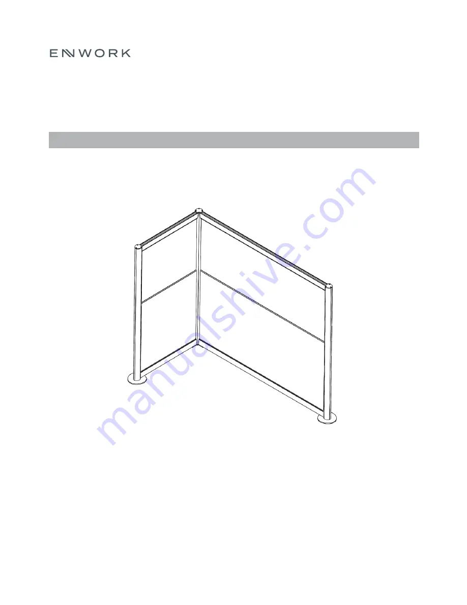
S C R E E N I N S T A L L A T I O N G U I D E
S C R E E N S
Z I 0 0 0 2
Page 1: ...Zori Freestanding L Shaped Screens Installation Guide Rev A Z O R I F R E E S T A N D I N G L S H A P E D S C R E E N I N S T A L L A T I O N G U I D E S C R E E N S Z I 0 0 0 2 ...
Page 2: ... L U D E D Pre Assembled Panel Bottom Plate FRM 1911 Stretcher Upper FRA 2065 xx Lower Panel Laminate FRL 1876 xx Upper Panel Acrylic FRX 1046 or Acoustic FRX 1064 xx L Cap Plate FRM 1912 L Vertical Support Column FRA 2066 xx Stretcher Lower FRA 2065 xx Top Cap Plate CYM 1700 ...
Page 3: ...S T E N E R S I N C L U D E D C O N T Aluminum U Channel For Acrylic panel only FRA 2068 xx 5 16 18 X 75 Serrated Flange Head Cap Screw Joiner Biscuit For Acoustic panel only 10 24 x 1 Square Drive Flat Head Type F Screw 5 X 1 2 Flat Head Wood Screw Phillips ...
Page 4: ...I N S T A L L A T I O N G U I D E 2 T O O L S A N D S U P P L I E S R E Q U I R E D Drill Square Head bit in Wrench ratcheting recommended ...
Page 5: ...m the slotted end of the Vertical Support Column Set aside to be re installed later Install the Upper and Lower Stretchers and the Vertical Support Column using 4 5 16 18 X 75 Cap Screw Tighten the Lower stretcher bolt Snug the Upper stretcher bolt Slotted end This is to be dis assembled later F I G U R E 1 F I G U R E 2 F I G U R E 3 3 A S S E M B L Y ...
Page 6: ...tall 2 Bottom Plates and the L Cap Plate using 12 10 24 x 1 Square Drive Flat Head Lift the sub assembly and place it in the upright position Loosen the 2 5 16 18 X 75 Cap Screw and remove the Upper Stretcher Set aside to be re installed later F I G U R E 4 F I G U R E 5 F I G U R E 6 3 A S S E M B L Y ...
Page 7: ... and fasten using the supplied 5 X 1 2 Flat Head Wood Screws Install Panel Note The number of panels will depend on screen configuration NOTE For Acoustic Installation Place Joiner Biscuits into the routed slots of the Lower Laminate Panel and install the Acoustic panel F I G U R E 7 F I G U R E 8 F I G U R E 9 3 A S S E M B L Y ...
Page 8: ...cher and tighten the 5 16 18 X 75 Cap Screw from Fig 6 Reinstall the Cap Plate from Fig 2 Install Cap Plate CYM 1700 using 4 10 24 x 1 Square Drive Flat Head Install Upper Panel Assembly complete F I G U R E 1 0 F I G U R E 1 1 F I G U R E 1 2 3 A S S E M B L Y ...
Page 9: ...Specifications subject to change without notice Rev 07 2020 1 800 815 7251 www enwork com 12900 Christopher Dr Lowell MI 49331 ...