enware DET5071A-660B Installation And Maintenance Instructions Manual Download Page 1

Call 1300 369 273

www.enware.com.au

Enware Australia Pty Limited 

9 Endeavour Rd Caringbah NSW 2229 Australia 

Ph: 02 8536 4000   info

@

enware.com.au

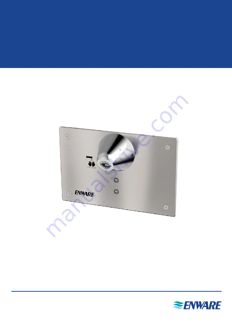
Enware Touch-Free Wall Sensor Tap 

- Active Sense with Detention Basin Spout

Installation and Maintenance Instructions

I00379_Sep21

DET5071A-660B

Summary of Contents for DET5071A-660B

Page 1: ...Australia Pty Limited 9 Endeavour Rd Caringbah NSW 2229 Australia Ph 02 8536 4000 info enware com au Enware Touch Free Wall Sensor Tap Active Sense with Detention Basin Spout Installation and Maintena...

Page 2: ...id valve remains open for more that 45 seconds the unit will time out and close the valve automatically This is intended to conserve water and prevent overflows COMPONENTS The wall sensor tap kit come...

Page 3: ...AS NZS3500 Installations not complying with PCA and AS NZS 3500 may void the product and performance warranty provisions Reference should also be made to the Australasian Health Facility Guidelines A...

Page 4: ...and will not operate Up to 1 5 metre clearance may be necessary from reflective surfaces such as ceramic tiles and stainless steel directly in front of and parallel to the front face of the sensor An...

Page 5: ...re as this will void warranty BEFORE CONNECTING WATER SUPPLY Ensure all supply lines are flushed thoroughly to remove debris prior to the installation of this product Strainers 40 mesh are recommended...

Page 6: ...olenoid and an isolation valve and a mesh strainer should be fitted before the solenoid for ease of servicing and trouble free solenoid operation SEE IMAGE 01 installation ISOLATION VALVE AND MESH STR...

Page 7: ...to the outlet side of the solenoid and supply line to the inlet side of the solenoid SEE IMAGE 01 INSTALLING THE SENSOR BRACKET Once the position of the spout and sensor plate is determined fix the s...

Page 8: ...f Solenoid Cable are pre wired to the cable plug to connect to the two side terminals on solenoid Earth terminal on top connector is not used SEE IMAGE 07 SOLENOID CONNECTION Connect here Connect here...

Page 9: ...nut Loosen grub screw on the spout slide onto wall base then tighten the grub screw to fix the spout in position TESTING Turn on the power to the unit and test the unit See Operating Instructions over...

Page 10: ...TURN ON Hover hand in front of sensor Water starts to flow TO TURN OFF Pull hand away Water flow stops after 6 seconds Maximum continuous run time per sensor activation is 45 seconds Security Time Ou...

Page 11: ...er does not turn on when hand is within sensor range Red LED does not light up in the sensor lens Power supply is off or transformer is damaged Turn power on or replace transformer Sensor is damaged R...

Page 12: ...solenoid 1 2 WMS8302 Transformer DC 24v with 4 5m lead EMDS802 Sensor Connector Cable 0 1m 673830 Solenoid Cable 3m 673829 2m Extension Cable for Transformer or Solenoid EMDS801 4 5m Extension Cable f...

Page 13: ...solenoid 3 The solenoid can be disassembled and checked for debris or damage to the diaphragm Refer to Servicing the Solenoid instructions below Take note of the location of the components so that it...

Page 14: ...d Grease can deteriorate over time and cause the solenoid to malfunction 8 Reassemble the plunger with spring into the core tube Check that the spring is reassembled back together inside the core tube...

Page 15: ...cable This cable is connected to the sensor 3 Take note of the installation firstly to determine if additional cable extensions are required additional to the 4 5 metres and secondly to see if cable...

Page 16: ...ansit or transportation making a claim To make a claim under this warranty you must notify us in writing within 7 days of any alleged defect in the product coming to your attention provide us with pro...

Reviews: