background image

Software Release:  [App: 02.09.10039.00; Config: 2.9.20024; Built in PowerVision Configuration Studio Version: 

2.9.23042; BTL: 02.09.10015.00]


Section 40   


61 


00-02-0996 

2019-06-13 

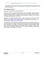
menu is present and is able to be changed. This security level allows the OEM full access to every menu 
item while setting up the controller for a particular engine and/or application where the OEM may not want 
the user to have access.


PC Configuration Software 

PowerVision for Controllers (PC Configuration Software) 

The  MPC-20 

controller  is  released  utilizing  Enovation  Controls’  PowerVision  Configuration  Studio

®

.  

PowerVision  allows  engineering  the  ability  to  deliver  quicker  software  updates  with  the  flexibility  of  a 
software  developer’s  environment.  The  addition  of  PowerVision  gives  Enovation  Controls  the  ability  to 
provide a free-of-charge basic PC configuration program (PowerVision for Controllers) to all customers for 
changing default parameters within the controller.  
 
PowerVision  for  Controllers  allows  fast  changes  of  default  menu  settings,  customer  splash  screen, 
parameters in the 6-up gauges screens, security levels, and text strings within the controller for a ready to 
load and go setup. PowerVision for Controllers is available via download from our support website. 

Login or Register for an Account to Access Downloads


Customers requiring a software developer’s environment for changing or adding further functionality into 
the controller may do so in their own time without waiting or paying non-recurring engineering fees (also 
referred to as NRE) to make changes

. This developer’s environment is PowerVision Configuration Studio

®


and requires purchase of the software license from Enovation Controls. PowerVision Configuration Studio

® 

allows custom software changes to almost all aspects of the controller from languages, screen layouts, text 
strings,  Modbus  communications,  CAN  communications,  IO,  faults,  state  machines,  activity  diagrams 
(visual scripting), and menu building to name a few. 


Summary of Contents for MURPHY PowerCore MPC-20-R2

Page 1: ... 02 0996 2019 06 13 Section 40 PowerCore MPC 20 R2EngineController OperationsManual Approved by CSA for non hazardous locations Group Safety Publication EIC 61010 1 Third Edition Products covered in this document comply with European Council electromagnetic compatibility directive 2014 30 EU and electrical safety directive 2014 35 EU ...

Page 2: ...t you use independent external protective devices to prevent potentially dangerous or unsafe conditions Assume that the MPC 20 R2 can fail with outputs full ON outputs full OFF or that other unexpected conditions can occur Please read the following information before operating the MPC 20 R2 Observe all Warnings and Cautions in each section of these instructions The MPC 20 is designed for use in in...

Page 3: ...gnizant at all times of hands and other objects that are in close proximity to the machine s being controlled as they may commence operation suddenly and without warning LENS CLEANING PROCEDURES The lens on the MPC 20 is composed of polycarbonate materials Use only mild soap and water to clean the lens display window Evidence of improper cleaning techniques or chemicals includes cracks smear marks...

Page 4: ...Software Release App 02 09 10039 00 Config 2 9 20024 Built in PowerVision Configuration Studio Version 2 9 23042 BTL 02 09 10015 00 Section 40 00 02 0996 2019 06 13 iv THIS PAGE INTENTIONALLY LEFT BLANK ...

Page 5: ... 15 Auto Throttling Functions Defined 15 Running Loaded Throttle 15 Pressure Level or Flow Transducer Throttle 15 Local Throttle Input 15 Quick Start Setup Guide 15 Setting up for a Mechanical Engine 16 Setting up for an Electronic J1939 Engine 16 Adjusting Screen Contrast 17 Setting up to Auto Start Stop for Single Contact Input Single Float 17 Setting up to Auto Start Stop for Start Local Key 17...

Page 6: ...Security 28 Engine Settings Low Security 30 Advanced Engine Settings Low Security 32 Throttle Menu Medium Security 37 Input Output Menu Medium Security 38 Application Configuration Medium Security 43 Start Stop Timers Low Security 48 Communication High Security 49 Passcodes High Security 50 Load Configuration High Security 50 Communications 51 Modbus Registers 51 CAN Parameter Map 51 Supplementary...

Page 7: ...ange the input type for the analog inputs use additional analog inputs as digital ground inputs assign functions and actions to digital inputs use digital inputs as battery or ground inputs be mounted in all weather environment be customer mounted in panel of choice Engine Application States and Delays While reprogrammable the MPC 20 follows a standard operating sequence This operating sequence is...

Page 8: ...o mode only a timed state that will allow the engine to run at a desired warm up RPM after starting Line Fill 1 available in Auto mode only a timed state that will allow the engine to run at a desired Line Fill RPM and exit if the timer times out or the pressure set point for this state is reached This is commonly used when filling a discharge line to a desired pressure when a lower RPM is needed ...

Page 9: ...the start signal remains present Auto Key allows the operator to change from Auto to Manual or Manual to Auto Mode The MPC 20 R2 requires an acknowledgement from the user to place in auto mode from manual Alarm Silence Key allows the operator to temporarily silence the internal siren common alarm output and acknowledge active faults when an alarm or shutdown is present on the controller Manual Thr...

Page 10: ...e menu key Review section Passcodes to understand the menu level preset in the MPC 20 R2 The following screen will display to enter the passcode Low 1111 Medium 5311 High 3482 The passcode will be entered left to right Utilize the up and down arrows and press the Enter button after each correct number If you enter the wrong passcode it will reset the display to 0000 allowing you to restart the ent...

Page 11: ...ws the operator to set items such as the J1939 address claim for the controller ECU Source Address ECU hour select crank attempts crank disconnect speed clutch engage disengage speed run to destruct mode and other user specific engine settings Review Advanced Engine Settings under the Menu Glossary section of this manual for a full list and definition of each setting Throttle The Throttle menu all...

Page 12: ...art and or auto throttling controller Depending on which application is chosen in the menu there are certain auto start functions and auto throttling methods hidden that are not pertinent to the application chosen This automatic hiding feature allows for a simpler more intuitive controller menu in the MPC 20 Review Application Configuration under the Menu Glossary section of this manual for the fu...

Page 13: ...plications The MPC 20 allows for the compressor to start stop and maintain a desired pressure during operation The auto start functions and auto throttle methods to choose from are listed below Auto Start Stop Functions Single Contact Two Contact Maintained Two Contact Momentary Pressure Transducer Auto Throttle Methods Running Loaded Pressure Transducer Local Throttle Input Hose Reel Irrigation T...

Page 14: ...mers work in conjunction with other Start Stop types but independently as Start Stop functions If the engine is already running from a Start Stop type when a Start Stop timer occurs the Start Stop timer is ignored Once the engine is started by the Start Stop timer other Start Stop types will be ignored until the timer expires and a controlled shutdown occurs Communication The Communications menu a...

Page 15: ...enu allowing the operator to enter the appropriate values needed in the application Warnings and shutdowns for any of these types are in the Advanced Engine Settings under Warnings and Shutdowns Auto Throttling Functions Defined There are five automatic throttle functions in the MPC 20 R2 and are shown relative to the application chosen as shown in the application configuration section Each is det...

Page 16: ...utput and press Enter 16 Access Analog Inputs and assign one Analog input for Oil Pressure and one for Engine Temperature Press Enter to save the settings 17 Press Back and access Relay and Digital Outputs 18 Press down arrow to Relay1 6 or DO1 6 and assign desired outputs for Crank Fuel and Inc Dec outputs if throttle type selected was Inc Dec NOTE DO5 and DO6 are factory set to Throttle Decrease...

Page 17: ...u System Press down arrow to Contrast then press Enter 2 Utilize the Up and Down arrows to adjust the Contrast values of 0 to 255 and press Enter when the desired number appears 3 Press the Menu key to exit the Menu Setup screens Setting up to Auto Start Stop for Single Contact Input Single Float 1 Access Menu Application Configuration Press the down arrow to Auto Start Stop Function then press En...

Page 18: ... Setup then press Enter 11 Select the pressure input type to set up then press Enter 12 Set the offset of the 4mA if needed then press Enter 13 Now set the range of the transducer on the high side then press Enter e g 0 100 PSI transducer would show 4mA at 0psi and 20mA at 100 PSI 14 Refer to step 13 above if setting for a 0 5V or Suction Pressure 15 Press Back twice to get back to the main menu 1...

Page 19: ... Rate to set up then press Enter 11 Set the offset of the 4mA if needed to calibrate the low side then press Enter 12 Set the range of the transducer on the high side then press Enter e g 0 20 000 gal min transducer would show 4mA at 0 gal min and 20mA at 20 000 Gal min 13 Press Back twice to return to the main menu 14 Utilize the Up and Down arrows to select Advanced Engine Settings then press En...

Page 20: ... Set the range of the transducer on the high side then press Enter e g 32 F 150 F transducer would show 4mA at 32 F and 20mA at 150 F 13 Press the Menu key to exit the Menu Setup screens NOTE If an auto stop condition occurs during the warm up delay the controller will enter an auto stop sequence Setting up to Stop the Engine from Utilizing the Countdown Timer The MPC 20 R2 will only utilize this ...

Page 21: ...iguration Studio Version 2 9 23042 BTL 02 09 10015 00 Section 40 21 00 02 0996 2019 06 13 Screen Examples Additional Screens The main screen shown above displays actual and target RPM Oil Pressure Engine Temperature Battery Voltage Engine Hours Engine State and Mode of Operation ...

Page 22: ...creen shown above displays to the operator System Level Pump Oil temperature Pump Housing temperature Gear Box Pressure Ambient temperature and Flow Rate If alternate parameters are desired these may be changed within the free MPC 20 R2 Software Configuration tool The screen above displays the auto start stop type and illustrates the throttling method for the auto start stop This screen is a defau...

Page 23: ...for Regeneration request The screen shown is an example of the request for regeneration This request is sent once a second for 10 seconds It is up to the engine whether it accepts the request or denies the request Standard Regen Screen shown on left CAT Perkins shown on right The screen above displays the engine manufacturer date day time software version number shown as an example configuration v...

Page 24: ...analog input functions are set to without accessing the menu The screen above allows the operator to see what the digital output functions are set to without accessing the menu and the active setting which informs the user of the output status The screen above allows the operator to see what the relay status functions are set to without accessing the menu and the active setting which informs the u...

Page 25: ...ed to be shown the screen above provides a list of service reminders and the hours left until the internal alarm will display the services needed When 0 hours is reached the hours will continue to count down in negative numbers to indicate how far past the reminder the engine was run In the MPC 20 R2 controller the service reminder screen is defaulted to be hidden and all reminders are set to 0 Hr...

Page 26: ...en engine aftertreatment is in need of regeneration This is due to the aftertreatment filter reaching the engine manufacturer s set soot level for a regeneration to occur Displays when the Engine ECU has inhibited a regeneration from occurring This should also be shown when inhibiting regeneration selection is made in the menu Displays when an emissions aftertreatment malfunction has occurred Cont...

Page 27: ...w idle within 30 minutes JCB Deutz Emissions Malfunction Low JCB Deutz Emissions Malfunction High JCB Catalyst Tank Level below 15 JCB Catalyst Tank Level below 5 JCB DPF Emissions Filter Above 80 Engine Refresh Required JCB DPF Emissions Filter Above 90 Engine Overloaded JCB DPF Emissions Filter at 100 Engine Plugged JCB Inducement Level 2 3 or Final Also used as Malfunction Indicator Lamp This i...

Page 28: ...e set points or the bypass timer s within the MPC 20 to ensure the ranges are within normal operating settings prior to consulting the engine manufacturer Menu Glossary System Low Security Date Time Low Security allows the setting of the controller s date and time This is used for clock start stops and fault recording in event history Units Medium Security allows the setting of the units of measur...

Page 29: ... 30 00 Service Reminders Medium Security Show Service Screens Medium Security factory set to Hide Oil Life Medium Security factory set to 0 Hrs Reset Oil Life Medium Security resets Oil Life reminder to factory setting Oil Filter Life Medium Security factory set to 0 Hrs Reset Oil Filter Life Medium Security resets Oil Filter Life reminder to factory setting Belt Life Medium Security factory set t...

Page 30: ... Up in Auto Manual is set to Auto Factory set to Yes Green LED High Security allows the operator to set the green LED to illuminate when either in auto mode or when the controller is in the Running Loaded state Factory set to Auto Restore Factory Defaults Medium Security allows the operator to reset all menu settings set as defaults from the last configuration loaded in the controller Set Internal...

Page 31: ...rity shows the regeneration screen in the main screens when set to Yes Factory set to No NOTE Inhibiting the Regen may cause the engine to de rate or shut down if the soot level is too high Recommend leaving this setting in Auto Regen The ECU may not allow the Regen request if certain parameters do not meet the engine manufacturers requested levels Speed Source High Security allows the selection o...

Page 32: ...9 is selected for the Engine Type Factory set to 0 ECU Hour Select High Security choose from ECU Hours engine hours reported by the ECU or Internal hours calculated internally by the MPC 20 provided the RPM 50 This menu item is only shown if J1939 is selected for the Engine Type Factory set to ECU Hours Crank Attempts High Security format of 0 00 to 20 00 The number of times the engine will attemp...

Page 33: ...edium Security allows the selection of having Prestart 2 active during auto only Choose from Enabled or Disabled Factory set to Disabled Prestart Delay 2 Low Security after an auto start condition has been accepted by the controller this delay begins timing and the prestart 2 output turns on When this delay expires the output is turned off and the auto sequence continues Factory set to 00 00 00 Pr...

Page 34: ...re removed during this delay the delay resets to zero If the selected functions remain active throughout this delay the selected action for the parameter will occur Bubble Lockout Time Medium Security Factory set to 00 00 00 Bubble Lockout 1 Medium Security Factory set to Disabled Bubble Lockout 2 Medium Security Factory set to Disabled Bubble Lockout 3 Medium Security Factory set to Disabled Bubb...

Page 35: ...actory set to 210 F High Engine Temp Shutdown Medium Security shuts down the engine when the temperature of the engine reaches the set higher limit parameter for temperature Factory set to 225 F Low Engine Temp Warning Medium Security sounds a warning when the temperature of the engine reaches the set lower limit parameter for temperature Factory set to 32 F Underspeed Shutdown Medium Security shu...

Page 36: ...uts down the engine when the flow rate reaches the set low limit parameter for flow rate Selection only shown when an analog input is selected to monitor Flow Rate Factory set to 0 gpm High Discharge Pressure Warning Medium Security sounds a warning when the discharge pressure reaches the set high limit parameter for discharge pressure Selection only shown when an analog input is selected to monit...

Page 37: ...edium Security shuts down the engine when the pump oil temperature reaches the set high limit parameter for pump oil temperature Selection only shown when an analog input is selected to monitor Pump Oil Temperature Factory set to 32 F Throttle Menu Medium Security Engine Throttle Type High Security allows the selection of J1939 TSC1 Pulse Inc Dec Analog 0 5VDC or None as the throttle type for the ...

Page 38: ...ngine response or decrease this value for faster engine response Factory set to 250 mS Analog Minimum Value High Security only appears when analog throttle type is chosen analog throttle output will not go lower than this set point Factory set to 50 V Analog Maximum Value High Security only appears when analog throttle type is chosen analog throttle output will not go higher than this set point Fa...

Page 39: ...erride User 1 through User 6 Speed 1 through Speed 5 Kubota Parking Brake needed when Kubota engine and Tier 4 is selected Kubota Neutral Switch needed when Kubota engine and Tier 4 is selected Pivot Alignment allows a warning or shutdown when a pivot becomes misaligned Disable TSC1 allows the operator to disable the TSC1 message to the engine when active Remote Throttle Active allows the operator...

Page 40: ... 8 Medium Security for each of the analog inputs the ability to select the following parameters exists Analog input 1 Factory set to Disabled Analog Input 2 Factory set to Disabled Analog Input 3 Factory set to Disabled Analog Input 4 Factory set to Disabled Analog Input 5 Factory set to Disabled Analog Input 6 Factory set to Disabled Analog Input 7 Factory set to Disabled Analog Input 8 Factory s...

Page 41: ...bient Temp Sensor Sensor Setup Medium Security only appears when the analog inputs are configured This sets the range of sensors for 4 20mA or 0 5V senders Oil Pressure 0 5V or 4 20mA Ambient Temp 0 5V or 4 20mA by raising the minimum value 4mA or 0V in the sensor setup a negative Ambient Temperature can be read by the Controller in Celsius or a temperature below 32 degrees in Fahrenheit Coolant T...

Page 42: ... on when a fault shutdown occurs Common Alarm output turns on when either a shutdown or a warning occurs Remote Alarm output turns on when either a shutdown or a warning occurs Air Damper Normally De energized output turns off during the energize to stop delay Not in Auto output turns on when the controller is in the manual mode Air Damper Normally Energized output turns on during the energize to ...

Page 43: ...p s throttle in order to maintain a pressure in the hose during irrigation Frost Protection houses the auto start functions and auto throttle methods meant to be used on frost protection systems This application allows for wind machine sprinkler or other forms of frost protection using single contact or a temperature transducer Auto Start Stop Function Medium Security Factory set to Two Contact Ma...

Page 44: ...ype uses the PID adjustments found in the Transducer setups within the Application menu This setting should only be used by a technician who understands in detail the method of tuning the proportional integral derivative control loop commonly used in PLC programming language NOTE When selecting PID Auto Throttle as the auto throttle type the Ramp Inc Rate and Ramp Dec Rate in the Throttle menu sho...

Page 45: ... be throttled between the min and max RPM set points to maintain this pressure Factory set to 0 psi Deadband Pressure Medium Security extends above and below the maintain set point No throttling occurs while the pressure is in the deadband Factory set to 0 psi Pressure Type Medium Security Suction Discharge Discharge when the Auto Start Stop is selected as Pressure Transducer and the Pressure Type...

Page 46: ...ory set to 0 psi Pressure P High Security This selection is present when PID Auto Throttle Type selected and allows adjustment of the Proportional setting of the PID loop when throttling Factory set to 0 020 Pressure I High Security This selection is present when PID Auto Throttle Type selected and allows adjustment of the Integral setting of the PID loop when throttling Factory set to 0 020 Press...

Page 47: ...hrottle Type selected and allows adjustment of the Integral setting of the PID loop when throttling Factory set to 0 020 Flow D High Security This selection is present when PID Auto Throttle Type selected and allows adjustment of the Derivative setting of the PID loop when throttling Factory set to 0 001 Level Transducer Medium Security only present when selecting Level Transducer in the Auto Star...

Page 48: ...ion is present when PID Auto Throttle Type selected and allows adjustment of the Derivative setting of the PID loop when throttling Factory set to 0 001 Temperature Transducer Medium Security only present when selecting Temperature Transducer in the Auto Start Stop Function Start Temperature Medium Security when the temperature drops to this set point an auto start will occur Factory set to 32 F S...

Page 49: ...Register Map Factory Default Slave Address High Security the RS485 Modbus slave node number Factory set to 1 Serial Setup High Security allows the operator to change the controller s RS485 serial communication settings Baud Rate High Security Factory set to 19200 9600 19200 38400 57600 115200 Stop Bits High Security Factory set to 1 0 1 2 Parity High Security Factory set to None None Odd Even PVCA...

Page 50: ...to FAT and left in another format the file may not load correctly This menu allows the MPC 20 operator using the High Security passcode to select a file from a USB drive plugged into the programming harness for the controller Once the files are stored on the drive after generated in PowerVision for Controllers the file will show as long as the software was for the MPC 20 hardware and has the file ...

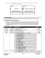
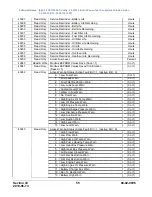
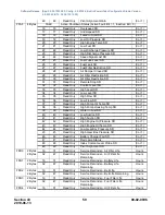
Page 51: ...ving register changes to the controller REGISTER TYPE DESCRIPTION UNITS 40001 40002 Read Only Current Engine Hours 32 Bit Hours 40003 Read Only Actual Engine Speed RPM 40004 Read Only System Voltage 12 5 will read 125 VDC 40005 Read Only Actual Engine Oil Pressure kPa 40006 Read Only Actual Engine Temperature Celsius 40007 Read Only Controller State Active State Numeral Indicated Numerals 0 ECU St...

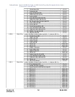
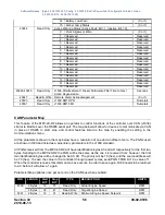
Page 52: ...s Active Fault Bit 1 Inactive Bit 0 0 Coolant Level SD 0 or 1 1 High Level SD 0 or 1 2 Low Level SD 0 or 1 3 High Flow SD 0 or 1 4 Low Flow SD 0 or 1 5 Reserved Reserved 6 Reserved Reserved 7 Water in Fuel SD 0 or 1 8 Low Suction SD 0 or 1 9 High Suction SD 0 or 1 10 Reserved Reserved 11 High Engine Oil Temp SD 0 or 1 12 Low Gear Box Pressure SD 0 or 1 13 High Gear Box Pressure SD 0 or 1 14 Reserv...

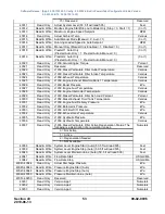
Page 53: ...ne Fuel Temperature Celsius 40028 Read Only J1939 Engine Intercooler Temperature Celsius 40029 Read Only J1939 Diesel Particulate Filter Ash Load Percent Percent 40030 Read Only J1939 Diesel Exhaust Fluid Tank Temperature Celsius 40031 Read Only J1939 Engine Fuel Delivery Pressure kPa 40032 Read Only J1939 Barometric Pressure kPa 40033 Read Only J1939 Air Filter Diff Pressure kPa 40034 Read Only J...

Page 54: ...erved 7 Reserved Reserved 8 Reserved Reserved 9 Reserved Reserved 10 Reserved Reserved 11 Reserved Reserved 12 Reserved Reserved 13 Reserved Reserved 14 Reserved Reserved 15 Reserved Reserved 40214 Read Only Controller State Timer Seconds 40215 Read Only Target Engine Speed from Controller RPM 40216 Read Write All Purpose Auto Start Function Active Function Numeral Indicated Numerals 0 Single Cont...

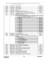
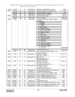
Page 55: ...r 1 40241 Read Only Modbus EEPROM Values Saved Confirmation Saved 1 0 or 1 40242 Read Only Active Warning Status Active Fault Bit 1 Inactive Bit 0 0 Low Fuel Warn 0 or 1 1 Fuel Leak Warn 0 or 1 2 Fuel Filter Restriction Warn 0 or 1 3 Low Lube Level Warn 0 or 1 4 Coolant Level Warn 0 or 1 5 Water in Fuel Warn 0 or 1 6 No Flow Warn 0 or 1 7 High Engine Oil Temp Warn 0 or 1 8 Low Oil Pressure Warn 0 ...

Page 56: ...ex To save the value in the controller through power cycles send PGN FFBB bit 16 a value of 1 When the controller receives this command a save occurs In order to save again bit 48 needs to be returned to a 0 before it will allow a 1 again Parameter Map updates once per second on the CAN bus when enabled PGN LENGTH Start BIT Stop BIT TYPE DESCRIPTION UNITS FF90 2 Bytes 16 31 Read Only Actual Engine...

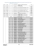
Page 57: ...s FF96 1 Bit 16 16 Read Write CAN Communication Start Stop Auto Stop 0 Start 1 0 or 1 FF97 1 Bit 16 16 Read Write Auto Manual Mode Manual 0 Auto 1 0 or 1 FF98 1 Bit 17 17 Read Write Manual Only Manual Only Active 1 Auto and Manual 0 0 or 1 FF99 1 Bit 18 18 Read Write Prestart 1 Auto Only Prestart Auto Only 1 Prestart Auto Manual 0 0 or 1 FF9A 1 Bit 19 19 Read Write Prestart 2 Auto Only Prestart Au...

Page 58: ...be Level Warn 0 or 1 20 20 Read Only Coolant Level Warn 0 or 1 21 21 Read Only Water in Fuel Warn 0 or 1 22 22 Read Only No Flow Warn 0 or 1 23 23 Read Only High Engine Oil Temp Warn 0 or 1 24 24 Read Only Low Oil Pressure Warn 0 or 1 25 25 Read Only High Engine Temp Warn 0 or 1 26 26 Read Only High Discharge Pressure Warn 0 or 1 27 27 Read Only Low Discharge Pressure Warn 0 or 1 28 28 Read Only H...

Page 59: ... 0 or 1 35 35 Read Only High Flow SD 0 or 1 36 36 Read Only Low Flow SD 0 or 1 37 37 Read Only High Pump Oil Temp SD 0 or 1 38 38 Read Only High Pump Housing Temp SD 0 or 1 39 39 Read Only Water in Fuel SD 0 or 1 40 40 Read Only Low Suction SD 0 or 1 41 41 Read Only High Suction SD 0 or 1 42 42 Read Only High Engine Oil Pressure SD 0 or 1 43 43 Read Only High Engine Oil Temp SD 0 or 1 44 44 Read O...

Page 60: ...it 16 16 Read Write Remote Alarm Acknowledgement 0 or 1 Supplementary Information Passcodes The MPC 20 R2 controller houses three levels of passcode protection This feature allows the OEM technician or owner to set desired menu parameters to be shown and changed only by selected operators The three levels are low security medium security and high security The default passcodes can easily be change...

Page 61: ...customers for changing default parameters within the controller PowerVision for Controllers allows fast changes of default menu settings customer splash screen parameters in the 6 up gauges screens security levels and text strings within the controller for a ready to load and go setup PowerVision for Controllers is available via download from our support website Login or Register for an Account to...

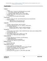
Page 62: ...nfigurable 4 20 mA 0 5V resistive or digital ground o 1 Frequency supporting Magnetic pickup 30 Hz 10 kHz 2 0 VAC 120 VAC and Engine Alternator 30 Hz 10 kHz 4 5 VRMS 90 VRMS Outputs 13 o 6 Relay Form C dry volt free 10A 30 VDC 10A max 40A maximum aggregate 85C o 2 Low side FET DC 1A o 2 High side FET DC 2A o 2 5V 200mA available to drive external 5V relay coils o 1 Analog 0 5V Dedicated for Analog...

Page 63: ...Software Release App 02 09 10039 00 Config 2 9 20024 Built in PowerVision Configuration Studio Version 2 9 23042 BTL 02 09 10015 00 Section 40 63 00 02 0996 2019 06 13 THIS PAGE INTENTIONALLY LEFT BLANK ...

Page 64: ...Software Release App 02 09 10039 00 Config 2 9 20024 Built in PowerVision Configuration Studio Version 2 9 23042 BTL 02 09 10015 00 ...

Reviews: